LMH6552: Output polarity doubts

Part Number: LMH6552
Other Parts Discussed in Thread: THS4551

Hi,

I am designing a prototype that works with differential signals. This signal passes through several components, and after an FDA driver implemented with the LMH6552, it needs to be fed into a band-pass filter, such as the one generated using the FilterPro tool:

 BPF.jpg

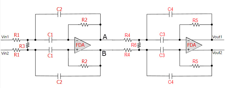
The attached BPF is a 4th-order Butterworth filter using an MFB topology. As shown in the schematic, the positive output “out+” of the first FDA (node A) feeds the negative input of the second FDA. My understanding is that this introduces a 180-degree inversion in the differential polarity.

Given that, how should I connect the polarity of my differential signal to the filter inputs Vin1 and Vin2? Should I connect the positive output of my FDA to Vin1 to obtain an overall 360-degree phase relationship? Or should I instead connect the positive output to Vin2 and the negative output to Vin1?

  • Hello Aitor,

    You have asked a great question.  Your thoughts and process are correct, there will be a 180 degree phase shift per amplifier if both of the following conditions are observed:

    - The differential input voltage, Vdiff_in, is the difference in potential between Vin1 & Vin2 as expressed: Vdiff_in = Vin1 - Vin2

    - The differential output voltage, Vdiff_out, is the difference in potential between Vout1 & Vout2 as express: Vdiff_out = Vout1 - Vout2

    Voltage and potential energy are referenced relative to a selected potential.  This can be ground, a bias voltage, a supply voltage, etc.  In this FDA circuit, the phase shift occurs as you described it (Input + 180 shift + 180 shift = Output) if you keep the reference of the differential input & output voltages the same.

    Let us use an example: perhaps we want to drive the differential inputs to a data converter (true fully-differential inputs, not single-ended or psuedo-differential input ADC).  The ADC would have a positive and negative input, something like AINfor analog input negative and AINfor analog input positive.  The polarity observed by the ADC (or any FDA in the differential signal chain) is determined by how you choose to connect the signals.

    If Vout1 is connected to AINP, the data converter will see the waveform from Vin1 360 degree phase shifted (so, in essence, not shifted) and treat this signal as the positive differential waveform.  The resulting AINN connection to Vout2 would provide the phase-shifted 180 degrees inverted copy of the signal to the ADC.  If you swapped Vout1 and Vout2 so Vout1 connects to AINN, the ADC would see a 180 different phase shift than in the example where Vout1 connects to AINP.

    Even in your FDA stage before your Butterworth filter, how you connect the outputs of the FDA to the LMH6552 active filter can determine the polarity of the signal at the ADC.

    If you want to follow convention or keep it simple, a differential signal being input into this active filter (in your above example) and connected to a data converter with Vout1 connecting to AINP (or positive input equivalent) would result in there being only one phase shift: the original FDA phase shift before the filter (the 180 phase shift from the input FDA driver).  This 180 phase shift may not be observed if you are driving a single-ended input into the positive (noninverting) FDA input and taking the differential output from the negative output as your positive piece of the differential signal.

    The summary: you choose how you connect and reference your circuit voltages, including the related polarity and phase shifting.  I would suggest looking at an FDA (does not need to be LMH6552, could be our THS4551) in a TINA or PSPICE simulation and exploring how you measure and connect the signals together.

    Please let me know if you have any additional questions.

    Best,

    Alec

  • Thank you Alec for your reply. 

    You help me to understand better the polarity issue. So, if I understood well, I have to play with the signal polarity of my signal in Vin1 and the connection from Vout1 to AINP or AINN to get the desired shift. In my case, I would find the 360º shift. 

    Thank you again. 

    BR.