This thread has been locked.

If you have a related question, please click the "Ask a related question" button in the top right corner. The newly created question will be automatically linked to this question.

INA237: INA237 Usage Questions

Part Number: INA237
Other Parts Discussed in Thread: TIDA-00313

Hello,

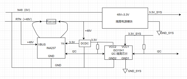
We have a new design using TI's INA237, as shown in the diagram below:

  1. Is it possible to detect the voltage on RTN?

  2. Can VBUS be connected to 48V and GND be connected to -48V?

  3. Is isolation design required?

Could you please help review this? Thank you.


ScreenShot_2026-04-21_111440_901.png

  • Hello,

    If you have GND on -48V and BUS and common mode voltage at 48V, then that is a difference of 96V. The INA237 can only handle 85V, so this setup as-is will not work. One way you can adjust it, is to have the Rsense on the low side, and divide the RTN down to be within 85V of the INA ground (then use the divide factor to adjust relevant results).  Yes, isolation will be required in this setup unless you have the INA ground at 0V (ie, same as MCU). Here is a reference design that does a similar thing: https://www.ti.com/tool/TIDA-00313. Side note, your "DCDC" says 3.3V, but it needs to be 3.3V above GND, which would actually be -44.7V.

    Regards,

    Mitch

  • Thank you for your reply. Perhaps I did not clearly express my intention earlier.
    First, this is a communication power supply with a voltage of -48V.
    RTN is at 0V, and N48V is at -48V, so the voltage difference between them is 48V.
    Second: I want to monitor the current on RTN, with N48V serving as the reference ground.
    Therefore, the sense resistor (Rsense) is placed on the high side, which differs from the TIDA-00313 design. Could you please confirm whether my usage is correct?

    By the way, according to this configuration, both the input and output reference of the DCDC converter are set to N48V.
    So its output is +3.3V relative to N48V, correct?

    I have revised the diagram. Perhaps it can convey my intention more clearly.
    thank you again,and i look forward to your reply


  • Hello,

    Ok, thank you for the clarification, I see what you are doing now. Yes, this is fine to do. VBUS will read the voltage as +48V even though it is at 0V relative to the rest of the system, you will not need a divider or any scaling factor. From your description, the 3.3V should be fine also. 

    As a side note, I see that you have the INA237 connected to side 2 of the ISO. This is the correct way to do this, as side 1 will not have a compatible logic low level. I do recommend 33pF caps to GND from SDA and SCL on both sides of the isolator. 

    Regards,

    Mitch