This thread has been locked.
If you have a related question, please click the "Ask a related question" button in the top right corner. The newly created question will be automatically linked to this question.
Hi,
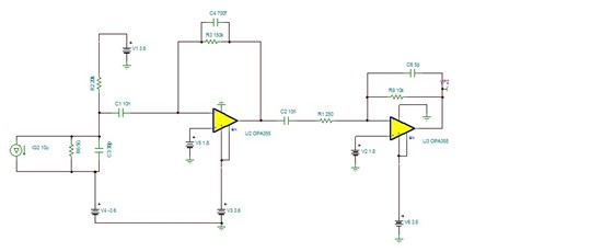
I have designed a TIA amplifier using OPA2355, the circuit works well, however there is one problem I need to address.
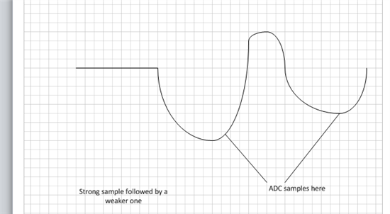
I get an input signal that is 1MHz, the transmitter turns on and off every 500nsec. However the transmit power of the transmitter is not coherent or linear. In one cycle it can be as high as 500mV swing (at the second stage output) and in the next cycle it can be 50mV. I get an overshoot if the weak signal is preceded by a strong signal. This is something I can deal in software but it has a high power tax, so I like to ask the gurus what are the changes I can make to to alleviate this problem or eliminate altogether.
My schematic is at the top.
Thx.
Frank,
Could you upload your TINA file to this thread? Also, what is the load that the second amplifier will be driving?
Thanks --
Bart,
Second amplifier is driving another set of OPA2355 acts as an active low pass filter. Those 2 followed by an ADC but there is RC in between which I will fix in next rev.
A graphical explanation of the problem is also below. These are two adjacent data sets. ADC samples only at the peak point. When I separate, you can see that the top measurement creates an overshoot on the bottom one. (Below one is the next measurement after top one) The blue is the raw data and the red is LP filtered. (In software) Look at the images.
It turns out the C2 in the schematic is not high enough to hold energy and cause DC level to shift between samples, I replaced the 10nF with 700nF and it works on simulation, I will report the real life results from here.
Thx,