This thread has been locked.

If you have a related question, please click the "Ask a related question" button in the top right corner. The newly created question will be automatically linked to this question.

Transimpedance amplifier with digital gain control.

Other Parts Discussed in Thread: LOG114, TINA-TI, REF5025, DAC9881, LF356, OPA381, OPA627, OPA637, OPA703

Hi,

I am doing a project on absorbance measurement using photodiode from Hamamatsu S1223. I need to design the transimpednce amplifier for the photodiode current signal using  an op amp having supply voltage of +/- 5V.The gain of the amplifier should be changed using a digital pot and the output is from 0 to 4V. Please recommend a suitable design.

Waiting for reply.

  • Sameer,

    Sorry for the late reply.
    LOG114, LOG102 seems what you are looking for absorbance measurement.
    The log ratio amplifier, LOG114, has two log amps for current input from photodiode followed by ratio amp. (Attached Fig.10 on spec sheet)

    TINA-TI simulation is available for LOG114. (Attached for one photodiode solution.)
     I1=1uA, I2=1mA,
     Vlogout = 0.375 x log(I1/I2) = -1.125V (TINA-TI = -1.18V)
     Vo4 = -0.249 x log(I1/I2) + 1.5V = 2.247V (TINA-TI = 2.28V)

    Although logamp may solve your requirement of gain control, if the measurement still needs external gain control, REF5025, DAC9881 with constant current circuit will be applicable. (Attached schematic will be connect to Pin4 of LOG114)

    If my understanding of your application is not correct, feel free to let me know.

    Best regards,

    Ichiro Itoi

  • Dear Sir,
    Thanks for your reply.
    Actually in my application I am doing the logarithmic conversion in software. That's why I asked you for a transimpedance amplifier digital gain controller. Presently I have built a transimpedance amplifer using OPA124 but its output is oscillating with supply voltage of +/- 12V. But I am thinking of using +/-5V of power supply. So which op amp will be suitable for it, so that its output should vary from 0 to 4095 mV.

    waiting for your reply.

  • Hi Sameer,

     It is good to know logarithmic conversion is in software. I was wondering if you could let us know transimpedance circuit you are using, so that we could simulate or estimate phase margin. And we would like to recommend op amp for +/-5V supply.

    I attached a simple circuit for example in a way to confirm size of photo diode capacitor, feedback resistor, and capasitor for stability.

    I attached a URL of blog by Bruce Trump about relationship between phase margin and overshoot.

                http://e2e.ti.com/blogs_/b/thesignal/archive/2012/09/10/spiceing-op-amp-stability.aspx


    Best regards,

     Ichiro Itoi

  • Hello Sir,

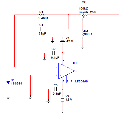
                  Recently I have tested the circuit around LF356 and I got the stable output. But I want to replace this circuit with +/-5 V power supply. I am thinking of using OPA381 transimpedance amplifier for this as it needs only +5V supply. Is this op amp is suitable or reccommend me a suitable amplifier.

    This is the circuit which I recently tested.


    Thanks & Regards

    Sameer Ramteke

  • Sameer

    I realize that your current application requirement is for an amplifier with split supplies of at least +/-5V.  However, if you ever only require 5V rail capability, I have a part that we are currently sampling that has very low input bias current on the front end (TIA) stage followed by a programmable gain amplifier stage.  We have provided access to the inverting and output pins of first amplifier so any TIA gain and filtering can be implemented.  the gain would then be fine tuned using the PGA in the second stage.  the second stage also has the benefit of being EMI hardened both at the inputs and supply pins.  The device also has a built in reference for level shifting or an external refernce can be used.  The last feature worth mentioning is the non-volatile memory for the gain setting.  The idea was to allow calibration in manufacturing for gain variations in the sensor using the PGA with non-volatile memory.  Once set, the device could be shipped with a sensor as a calibrated unit.  It is a very interesting part.  Let me know if you ever have a need for such a device.  Feel free to contact me directly at chuck.sins@ti.com if you need more details.

    Thanks

    Chuck Sins

  • Hi Chuck,

    Thank you for cover up and proposal of integrated solution.


    Hi Sameer,

    As per your circuit, let me share TINA-TI simulation result for different op amps.
    I will recommend OPA381 in terms of phase shift frequency and low input bias current.

     OPA124 IB=1pA  Phase shift 180 around 900kHz may cause oscillation
     LF356 IB=30pA  Low gin because of larger input bias current
     OPA381 IB=3pA  Phase shift 180 around 3.36MHz  ((recommend))
     OPA627 IB=5pA  Phase shift 180 around 2.06MHz
     OPA637 IB=5pA  Phase shift 180 around 1.17MHz
     OPA703 IB=1pA  Phase shift 180 at 405kHz

    Please note that photodiode equivalent capacitance is 10pF from S1223 spec sheet.
    As photo diode current is small, leak current may affect accuracy. Feedback route (C1, C2, R1) needs to be low leak as possible gain switch as well.

    If you have any questions, please feel free to let me know.

    Best regards,

    Ichiro Itoi