This thread has been locked.

If you have a related question, please click the "Ask a related question" button in the top right corner. The newly created question will be automatically linked to this question.

MUX - 4-20 mA

Other Parts Discussed in Thread: SN65HVS880, RCV420, ISO122, OPA365, OPA320

hello


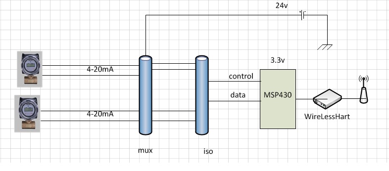
I'm developing a PLC with 3 inputs loop current (4-20 mA) for industrial use.

It has 3 modules interconnected by wirlesshart controlled by msp430.

My intention is to use a multiplexer for that purpose.

SN65HVS880

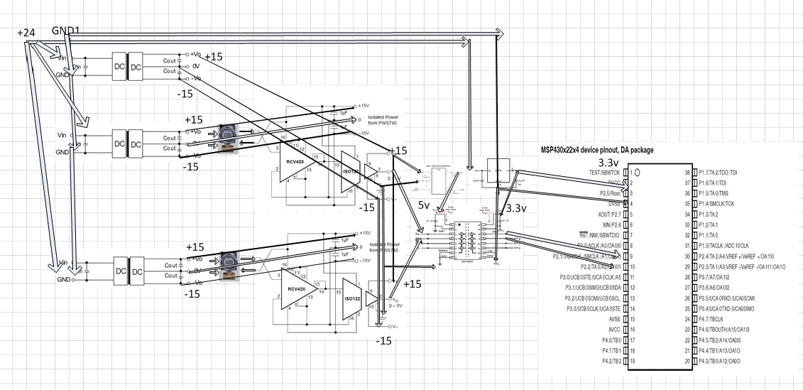
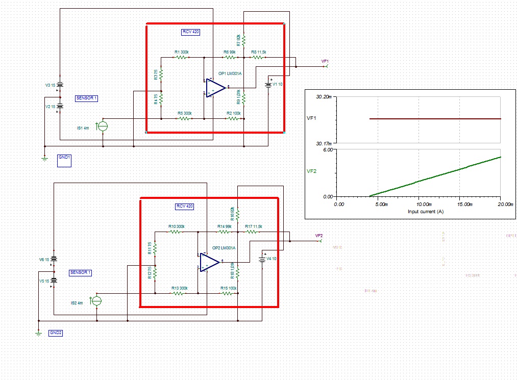
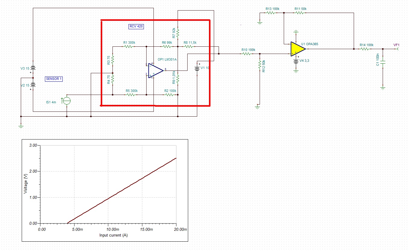
the loop current measure connected sensor by RCV420

Is correct use of these components?

Thanks & Regards,

  • Hi Juan,

    I'm having trouble understanding your requirements.  Are you multi-plexing the analog 4-20mA input signals or some type of communication interface?  Please provide a simple block diagram that may help us understand what you're doing.

    Thanks,

  • Hi Collin

    I'm trying to do this

    I'm thinking of using as mux to use a single source

    measure the current value and sent by msp

    24V supply provides power to sensors and msp without intervening in the value of loop current

    there is a component which can do this?

    I was clear in the  block diagram?

    Thanks, Juan

  • Hi Juan,

    I think I have a better understanding of what you're trying to do now and will try to summarize it below:

    You have a single MSP430 and 4-20mA recieving circuitry that you would like to share with two different remote 4-20mA sensors.  The goal of the system is to recieve the 4-20mA signal from the remote sensor and then wirelessly transmit data to/from it with a wireless HART system.  I am currently assuming that there is some distance between the MSP430 and 4-20mA receiving circuits but if they are located close to each other then please correct me.  I am also currently assuming that the MSP430 and wireless HART circuitry do not operate off of the same loop current as the 4-20mA sensors, once again please correct if this is wrong. 

    If the assumptions I've made above are correct then you will need two SPDT analog MUXes that will switch the loop-supply (+24V) and return (IOUT) signals between the two remote 4-20mA systems.  If you choose to leave the loop supply connected to both systems then you would only need to use one SPDT MUX to switch the IOUT return signals to and from your reciever but the inactive sensor will likely be in an unknown state due to the floating return signal.  To keep the inactive loop operational when it is not connected to the receiver a DPDT switch can be used to switch the IOUT return signals between the recieving circutry and a "dummy" load. 

    Since up to this point I've assumed that you will have a common receiving circuitry I believe you can avoid a MUX on the HART signal by injecting/monitoring it on the same side of the MUX as the reciever circuitry.

    TI has a modest portfolio of analog MUX ICs that you can choose from using the link below:

    http://www.ti.com/paramsearch/docs/parametricsearch.tsp?family=analog&familyId=1509&uiTemplateId=NODE_STRY_PGE_T

    I hope this helps.

    Regards,
    Collin Wells
    Precision Linear Applications

  • Collin thank you very much I will consider your comments, and running a simulation. Your considerations were correct.

    Regards

    Juan

  • Collin,

    I'm thinking about implementing the following circuit without using a mux.

    Is this a correct reading of the two current loop sensors?

    I'm trying to simulate the RCV420 but I cannot get the two curves correct.
    Is possible simulate in with two different ground planes?

    5824.RCV420X2.TSC

    Regards Juan

  • Hi Juan,

    I'm sorry to say that I can't really make out the images  you've attached.  Would you please upload them as a file instead of as an image?  If the first drawing was done in Visio you can send the original Visio drawing. 

    Regarding the simulation, what are your goals?  Let me know and I'll help you get something running.  When running a "DC Transfer Function" in TINA you can only use one source at a time, is that your issue?  Regarding your GND question, TINA electrically connects all nodes attached to the GND symbol.  If you want to use two different GNDs returns in a simulation then route everything without using the GND symbol.  As long as the electrical connections create a loop and current can return to the power-supply inputs then the simulation will work. 


  • Thanks for the response TINA software.

    With respect to the images, it is clarified that is a block diagram a little more in detail.
    Attached file in Visio.
    Developing reading 2 loop current sensors.

    Is correct the schematics ?

    0216.bloque.vsd

    Juan

  • Hi Juan,

    I must be confused regarding what you're trying to accomplish or this diagram simply doesn't make sense.  Here are a few notes:

    You have a lot of isolation and I'm not sure all of it is necessary.  For instance, you've isolated the isolated output of the ISO122......

    Also the ISO7240 is a digital isolator and will not work with analog signals from the ISO122, you will need an analog isolator if it's needed at all.

    Let's take a few (large) steps back.  Is this a remote-powered 2-wire sensor conditioning circuit that resides some distance from the "control room" or does this circuit reside in the "control room" where a local power and GND are available?

    The previous question will answer many of my questions but just to clarify another point, what all is powered from the +24V loop-supply / field supply input?   Is the MSP430 powered from the loop? 

  • The power supply is directly conected to mps430, but the sensors resides some distance away conected feed from the current loop.

    From what you've told me I can think of placing an operational amplifier limits the value I read 0-5v to 0-2.5 V for msp430.

    I am attaching the image. THE OPA365 is the most correct or can I suggest another model that works best.


    regards Juan

    0184.RCV420-OP.TSC

  • Hello Juan,

    I would go back with my original suggestion that all you need is a reciever circuit with a single SPDT MUX that switches the IOUT (RTN) of the two sensors back and forth.  The circuit you've shown would work for this.  You could consider the OPA320 as well as the OPA365.