Because of the holidays, TI E2E™ design support forum responses will be delayed from Dec. 25 through Jan. 2. Thank you for your patience.

This thread has been locked.

If you have a related question, please click the "Ask a related question" button in the top right corner. The newly created question will be automatically linked to this question.

oscillation in a low bandwidth(300Hz) trans impedance circuit

Other Parts Discussed in Thread: OPA4131, TINA-TI, OPA131, OPA27

Hey,

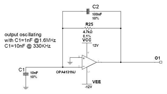
I'm now working on a trans impedance circuit using OPA4131(please see the following schematic), the bandwidth is set pretty low @ 330Hz, but the circuit oscillates (~3MHz) with a 10 meter long input cable (just a cable no sensor attached) which was measured having around 500pF capacitance. Then I intentionally tried C1 as 1nF (oscillating @ 1.6MHz, 2Vpp), 10nF (oscillating @ 330kHz, 4Vpp) and 100nF (no oscillation).  All capacitors used are ceramic 0603.

It seems very weird to me because according to the application note "BOA055A", with the compensation capacitor C2 equals to 100nF, C1=500pF, 1nF, 10nF or even 100nF should be far away from the condition that would cause an oscillation. Because fz is around 160Hz~330Hz (very far away from the open loop bandwidth of OPA4131 which is 4MHz) and fp is very close to fz.

Could anyone help to explain what is happening to the circuit and why it's oscillating while it's not supposed to be? Thanks a lot!

PS: I tried a way cheaper MC33174 in the same circuit, 10 meter cable, 1nF, 10nF, 100nF all are fine, no oscillation at all. While the offset voltage is higher and not suitable for the application.   

Regards,

Qi

  • Hi Qi,

    I think you have two issues that are colliding which is why you're having trouble designing this circuit.  Amplifiers go unstable due to two primary causes:

    1.)  Capacitance on the summing node (inverting input)

    a.)  This is the primary cause of oscillations in most transimpedance circuits with a photodiode or other diode as an input source. 
    b.)  The solution to this circuit is to include a capacitor across the feedback resistor as described in the app note you reference.

    2.) Capacitance on the output

    a.)  This is a very common circuit occurence either intentionally created in a voltage reference buffer, or accidentally created such as in a cable-drive or MOSFET drive circuit.

    Anyways, you have both of these issues occuring in your circuit which is why a standard compensation technique is not working.  Increasing the capacitance of C1 creates an effective "noise-gain" circuit which is likely causing the loop to close before the region that has been affected by the capacitive load. 

    You will need to compensate the 500nF drive circuit first and then design the transimpedance section or split the design into two stages where the first stage is the transimpedance amplifier and the second stage is the cable drive circuit. 

    I will do some work in TINA SPICE and send you a few files for your review.

  • Hi Collin,

    Thanks for your feedback, one thing I need to clarify: actually the cable I'm talking about is the input cable which is equivalent to C1=500pF.

    The OPA is not driving any capacitive load at the output.

    Qi

  • Hi Qi,

    Okay, thanks for the update, that drastically changes my analysis.  Let me do some Bode work in SPICE and I will send you a few example files for you to review.  Please download TINA-TI so you can view the simulation files. 

    http://www.ti.com/tool/tina-ti

  • Hi Qi,

    With 500pF - 1nF of capacitance, the appropriate feedback capacitor value is between 100pF - 150pF.  When you include the 100nF you create an effective capacitive load on the output of the amplifier of 1nF in series with 100nF which is equates to 990pF of load capacitance which is too much for the OPA131 to drive directly. 

    The 990pF of capacitve load results in a diminished phase margin of only 20 degrees which is much lower than the recommended range of 45 - 60 degrees.  Decreasing the capacitor to a more appropriate value as described in the app note results in a phase margin of around 70 degrees. 

    Increasing the capacitor to a very large value doesn't do you very much good in this circuit because the output noise will be based on the noise gain of the circuit which can not be lower than 0dB in this topology. 

    You can observe the AC Bode analysis for the original circuit with the issue and the modified circuit in the attached TINA files.  Try changing the values of Cin and Cf to see the effects of the Aol*B (Vfb) phase at the frequency where the Aol (Vo) and 1/Beta (Beta1) curves intersect.

    3125.OPA131_Qi_Wang_AC.TSC

    Original Circuit: 
    Cin = 1nF, Cf = 100nF:


    Cin = 1nF, Cf = 150pF:

    Cin = 500pF, Cf = 150pF:

    Hope this helps.

  • Hi Collin,

    Understood, while it seems the OPA4131 has pretty large equivalent Ro, but in the datasheet it states "EXCELLENT CAPACITIVE LOAD DRIVE".

    Anyway we choose the Cf =100nF for the following reasons:

    1. Cf serves as an ESD protection method, because the circuit is directly connected to a remote sensor

    2. The noise we are concerning is the high frequency noise coupled from the long sensor cable which is part of the signal itself, so signal gain takes effect.

    If we take the above two thoughts into account, do you have any suggestion for us, for example a more suitable OPA, thanks?

    -----------------------------------------------------------

    Our general requirements for the OPA are:

    power supply : dual, +/-12V

    V_in_offset < 500uV max (-40~85C)

    I_in_offset + I_in_bias < 100nA max (-40~85C)

    bandwidth: not important, the signal bandwidth in Hz range, amplitude 1uA~200uA

    decent capacitive load capability, say 500pF, because of the cable

    Regards,

    Qi

  • Hi Collin,

    BTW, do you think the phase margin should be around 50 degree instead of 71?

  • Hi Qi,

    I'm still working on a solution to your circuit design, but I can answer this quickly.

    No, the phase-margin is 71 degrees and is a measure of the loop-gain (Aol * B) phase when the loop-gain (Aol * B) magnitude crosses 0dB.  This is also the same frequency that the Aol and 1/Beta curves intersect. 

  • Hi Qi,

    Okay, here are some answers / comments to your previous post:

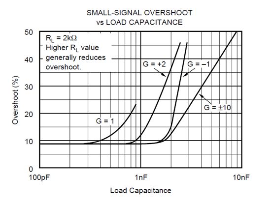
    The OPA131 does have excellent capacitive load drive compared to similar amplifiers.  Maintaining stability above a few 100pF is usually not possible with precision small-signal op-amps and the OPA131 does well up to several hundred pF in a buffer configuration and even better when configured for gain.  The capacitive load drive of the OPA131 is shown in the figure I've copied below. 

    One of the difficulties with the transimpedance circuit is that from a stability point of view it has a gain of +1V/V which is the least robust configuration you can place an amplifier in when stability is a concern.  Notice that we don't recommend driving a capacitive load greater than 900pF in a unity-gain configuration. 

    I understand your reasoning for the 100nF capacitor and if there's no way around it then unfortunately the only amplifier I could find that performed decently in the configuration you've defined is the OPA27.  It meets the specs you've listed below with the exception of the Ibos + Ib < 100nA max spec.  You will see the benefit of lower noise performance than the FET input amplifiers that have much lower bias current.

    -----------------------------------------------------------
    Our general requirements for the OPA are:
    power supply : dual, +/-12V
    V_in_offset < 500uV max (-40~85C)
    I_in_offset + I_in_bias < 100nA max (-40~85C)
    bandwidth: not important, the signal bandwidth in Hz range, amplitude 1uA~200uA
    decent capacitive load capability, say 500pF, because of the cable
    -----------------------------------------------------------

    Results:
    AC Bode Analysis:

    AC Signal Gain Analysis:
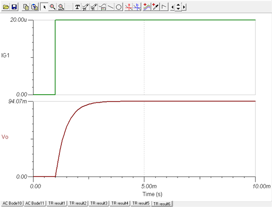
     Transient Step Response:

    2781.Qi_Wang_OPA27_AC_Bode.TSC

    8168.Qi_Wang_OPA27_AC_Signal.TSC

    5756.Qi_Wang_OPA27_Transient.TSC

    Hope this helps.

  • Hi Collin, thanks a lot!