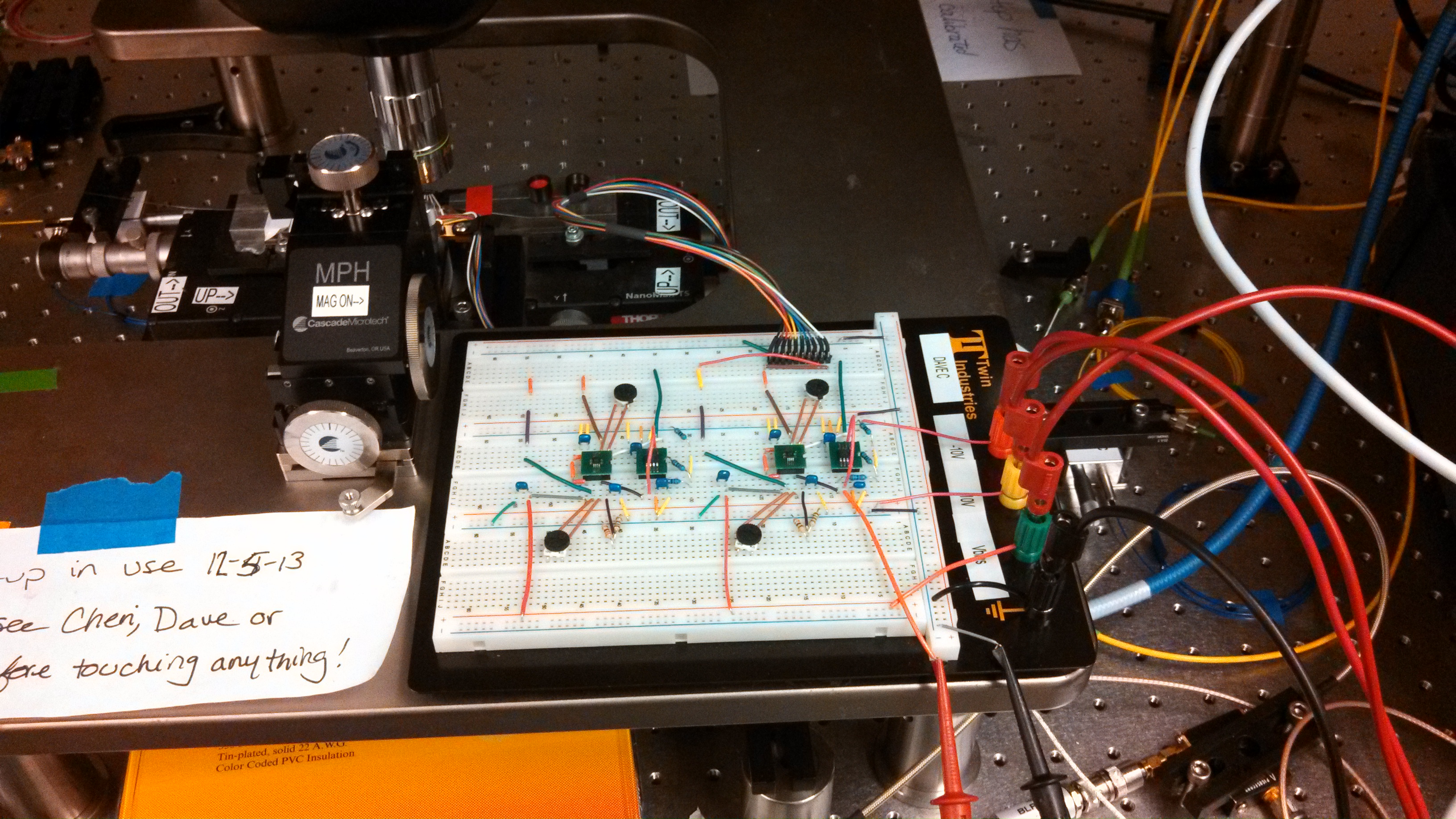
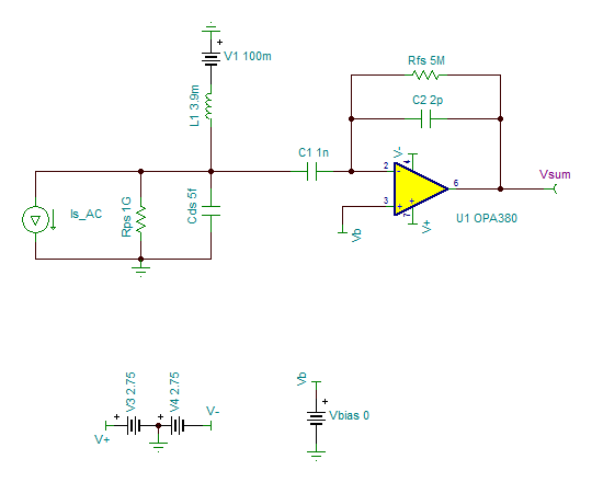
Hi all. I have an application where I have two pairs of detectors from a photonic chip. The goal is to run each detector pair through an OPA2380 and use the outputs as the inputs of the INA157. So my breadboard consists of two OPA2380s and two INA157s, one for each pair of detectors. A picture is attached. Unfortunately we have a relatively large DC component and a small AC component, so increasing the transimpedance gain to amplify the AC will only saturate the OPA2380. Ideally I would like to AC couple to the TIA, but I know that has some issues, given that the capacitor can cause the photodiodes to move into forward bias. Would it be possible to place a capacitor in series with the OPA2380 and an inductor in parallel to provide a DC path without effecting the bias point? The frequency of operation is relatively low, between 100kHz and 750kHz.
I've also noticed that when the OPA from the strongest detector pair is driven towards the positive rail, its AC signal is coupled to the power supply rails and hence appears at the second OPA2380. Power is being supplied by a three channel power supply. The positive supply is at +10V and powers the V+ of the INA157. The V+ of the OPA2380 is +5V and is derived from the +10V power supply output using a voltage divider. The -10V supply powers the V- of the INA157, and the V- of the OPA 2380 is connected to ground. Also, the four non-inverting inputs of the OPA2380s are also connected to ground to keep the diodes at a zero bias.
Lastly, I'm using 2k pulldown resistors to -5V, which is supplied by the third channel of the power supply. Granted, given that my DC component is so large that swinging to ground is not a problem, but at some point it may. Because the OPA2380 outputs feed the input of the INA157, is having the two 2K resistors in parallel at the 157 input a problem?
Thanks.
Dave