This thread has been locked.

If you have a related question, please click the "Ask a related question" button in the top right corner. The newly created question will be automatically linked to this question.

TLC272 mysteries death

Other Parts Discussed in Thread: TLC272, TPS6734

Hi

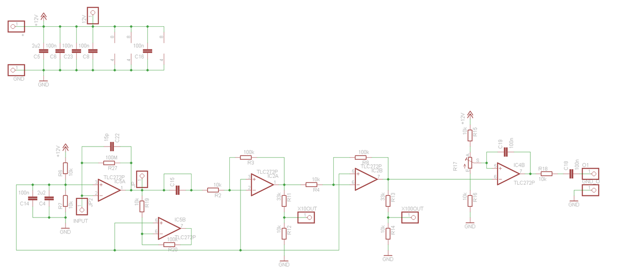
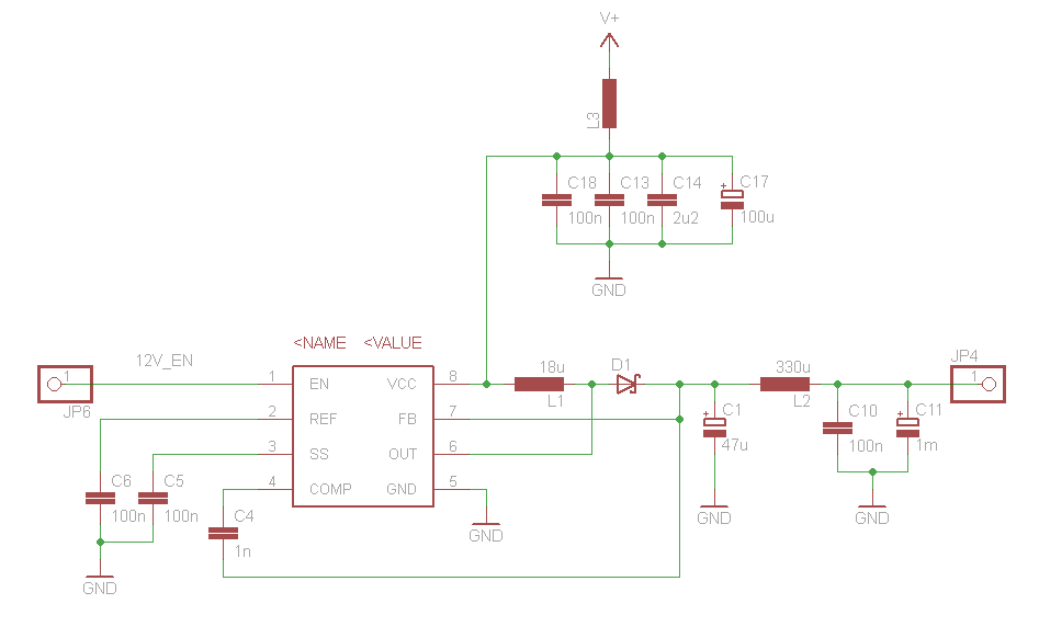
I have build a small test device with a TPS6734 12V step-up, a LC filter and 3 TLC272.

After a few hours of operation, all 3 opamps died and now show the same symptoms:

They work fine with a supply voltage < 9.5V. Otherwise the "latch up" and the bench supply current limit prevents worse things to happen.

In this "latched up" state the supply voltage drops to 2.8V (it feels like 4 PN junctions)  until i remove the power supply. I desoldered all three ICs and they all behave exactly the same.  I checked the ouput of the LC filter for overshooting or spikes, but it is very clean.

The circuit was in a shielded box without any inputs or outputs connected (apart from the bench power supply with 3.6V an 200mA limit), and was working perfectly befor.

Is this a typical failure mode? Does anyone know the reason for this?

Many Thanks

Lukas

  • Hello Lukas,

    The TLC272 should work reliably with a good +12 V supply. I do not see anything in the circuit schematic that raises immediate concerns. However, the fact that all three TLC272 amplifiers are dying in the same manner suggests the possibility of a supply-line electrical over-stress (EOS) voltage. You mention the output of the TPS/ filter output is very clean. Have you monitored it over the duration of your testing to make sure it doesn't exhibit any high-voltage transients? One thing you could try is adding a transient voltage suppresser (TVS) between the TLC272 VDD pin and ground. A 15 V TVS should be about right. If there are transients present it should clamp them to a safe level.

    You also mention that the input and output are not connected when the failure occurs. Have you checked the dc levels at each output when the power has been applied, and after the box has been on a while? Also, I would check each amplifier output with a 10x probe and O-scope for oscillation. Oscillating op-amps can self-destruct if the transistors in the output stage inadventently turn on at the same time. Should that happen the transistors draw too much current, self heat, melt, and short circuit.

    Let me know what you find.

    Regards, Thomas

    PA - Linear Applications Engineering

  • Many Thanks for the response. I set up a window trigger at 11.5V and 12.5V, but i didn't trigger in the last 6 hours. I put in 3 new TLC272 and couldn't see any oscillating op-amps.
    There is the possibility of 35V over a 10k Resistor to the input (IC5A pin2) , but this is a very unlikely scenario. I will monitor the pin and let you know if i find something

    I hoped that the failure mode would tell us what exactly died inside the chips.

    Kind regards
    Lukas
  • Hi Lukas,

    Thanks for the update. It is good you are monitoring the +VDD line. I would try cycling the power on and off and see if that generates any high-voltage spikes.

    If the IC5A inverting input had been subjected to a high over-voltage event - one that triggered a failure condition, it seems that would be the only amplifier damaged. The fact that all three amplifiers failed tends to suggest a common cause.

    Regards, Thomas

    PA - Linear Applications Engineering