This thread has been locked.

If you have a related question, please click the "Ask a related question" button in the top right corner. The newly created question will be automatically linked to this question.

about using LMH6629 as TIA

Other Parts Discussed in Thread: LMH6629, OPA355

hi, everyone.

I  am using LMH6629 as TIA(trans-impedance Amplifier). 

BUT it seems not work. my application is : receiving infra-red signal(wavelength~900nm), bandwidth range  from 2 to 8MHz. 

I can give some background info.  

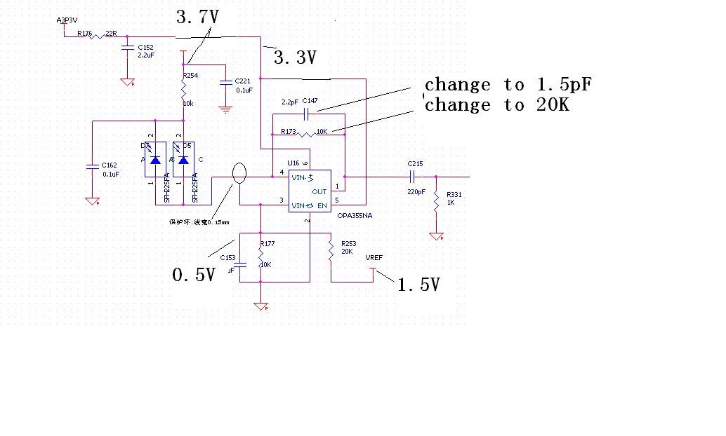
circuit topology is typical one, feedback resistor (20K) parallel with 1.5pF cap connecting output to inverting input,   non-inverting input is biased to 0.5V. a ~3.7V DC connecting to cathode of photodiode and anode to inverying input of OP. 

before using LMH6629,I used OPA355 which do works, in order to improve sensitivity, I think I need to fight against noise, so I choose a LMH6629 expecting get better sensitivity, but it fails.

comparing LMH6629 with OPA355 about bandwidth, noise performance.

LMH6629 has bipolar  input and (OPA 355) has FET input .  so LMH6629 has lower voltage noise and higher current noise......and much wide bandwidth and much higher input bias current.

the both parts package SOT23-5(-6). It is so easy to compare. when probing output of TIA for OPA355, I got a  peak at frequency domain on scope by Using FFT function, but for LMH6629, I got nothing at exact same setting-complete flat(no peak anymore).

I have no idea about what happen, do I  something wrong?

any answers will be appreciated. 

regards

PengYan

  • Hi PenYan,

    You don't mention it explicitly but I assume you are using the LMH6629 with a 3.7V single supply.

    If so, I recommend that you change the biasing on your non-inverting input from 0.5V to Vcc/2 (= 3.7V / 2 = 1.85V) instead when using the LMH6629. The reason is that the with no photodiode current, output voltage range of the LMH6629 requires about 0.8V of headroom to either supply rail (i.e. output can swing from 0.8V to 2.9V when using 3.7V single supply). The 0.5V you are using on the non-inverting input requires the output to swing down to 0.5V (with no photodiode current) which is not possible for this device.

    Also, I'm not sure what you are looking for the "FFT peaking" that you note. For evaluation purposes, I recommend that you first observe the operation using the oscilloscope in time-domain to make sure input / output node voltages are as expected and and that they move when they need to.

    Regards,

    Hooman

  • many thanks Hooman,

    Sorry for unclear mention, so I copy schematics here.

    1. single power is 3.3V --that is LDO output with 3.7V in.

    2. there are two reasons why 0.5V biasing  voltage on non-inverting input instead of VCC/2

    A) getting large photodiode voltage difference 3.2V--(3.7-0.5) to get less input cap(  fast reponse and less noise,wide bandwidth) 

    B) headroom is not issue, output of TIA always less than 20mV(following  TIA  there is a AGC ), 

    3. The reasons using frequency  domain just for  easy observing , at same time I can see waveform (combining with high frequency noise)in time domain.

     regards

    Pengyan

  • Hi PengYan,

    Thanks for the schematic.

    I understand that you like to maximize the voltage across the photodiode for faster response and for more headroom. However, the LMH6629 output voltage cannot swing down to 0.5V (it is limited to 0.80 V min and 2.4V maximum when used with 3.3V single supply, as copied below):

    So, maybe for testing purposes at first, find a way to bias the LMH6629 so that its input / output conditions are not violated. If biasing to Vcc/2 is not possible, here are other possibilities (which may not be practical in production but may be informative as experiments):

    1. Tie the LMH6629 V- pin to a negative potential (e.g. -1V or lower) to alleviate the issue with output voltage hitting the lower limit.

    2. For experimentation, change the non-inverting input to 1V (0.8V output headroom + 0.2V for your signal swing which is further towards V-) or higher and use > 4.2V  to your LDO input so that the photodiode Cathodes can be biased to a higher voltage and get the fast response you need.

    Let me know what you find out.

    Regards,

    Hooman

  • thank a lot, Hooman,

    I overlooked the important information that you mentioned. I will try it right now, feedback ASAP.

    Thanks again.

    PengYan
  • I am back, Hooman.
    You are RIGHT, I increased non-inverting input from 0.5V to 1.0V by swapping R177 and R253 in schematics above.
    YOU and TI e2e forum are very helpful to design engineers like me.
    Thanks you very much. pengyan