Because of the Thanksgiving holiday in the U.S., TI E2E™ design support forum responses may be delayed from November 25 through December 2. Thank you for your patience.

This thread has been locked.

If you have a related question, please click the "Ask a related question" button in the top right corner. The newly created question will be automatically linked to this question.

OPA1642 musical instrument input. Issue with AC coupling, signals with high slew-rate

Other Parts Discussed in Thread: LMH730123, OPA1652, OPA1642, TIPD186, OPA2171, LM324, LM358

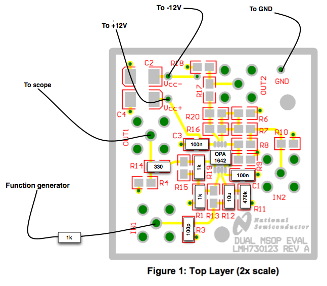
The schematic is that of appendix A (page 32) of TIPD186 - more precisely the input gain stage (U1A). This circuit has been built on a LMH730123 board (P1 replaced by a wire, so the expected gain is 2). Power supply is +/- 12V

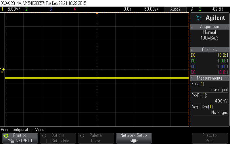
Sending a 8Vpp, 0V DC, 1kHz ramp signal straight from a signal generator to J1 through a 1k resistor, I observe that U1A's output has an unwanted negative DC offset of about -3V.

The problem goes away when C4 is shorted (but my application requires AC-coupling). Reducing the slew-rate of the waveform slightly alleviates the problem, but in my application the source impedance will be in the 1k to 100k range, thus I can't increase the value of C7 to filter the edges of the waveform before it hits the op-amp.

What causes this issue?

I could reproduce it with OPA1642 and OPA1652 (where the offset is even higher)

  • Hello Olivier,

    If the circuit is wired and operating properly you should not see such an offset at the output of U1A. In order to assist with this debug process, please provide the following:

    • The exact schematic of your circuit on the LMH730123 PCB
    • The exact source impedance, including that of the signal generator, present during your tests
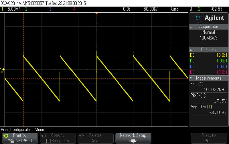
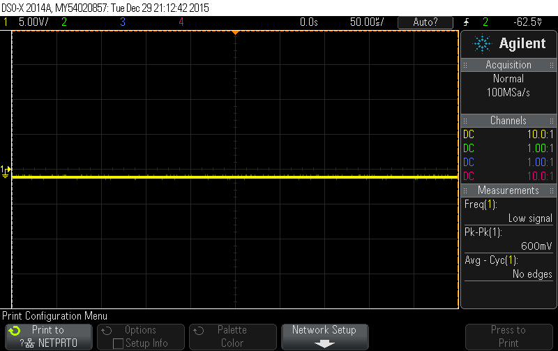
    • The oscilloscope capture of the output of U1A when the input is a constant 0V and when the ramp signal is applied
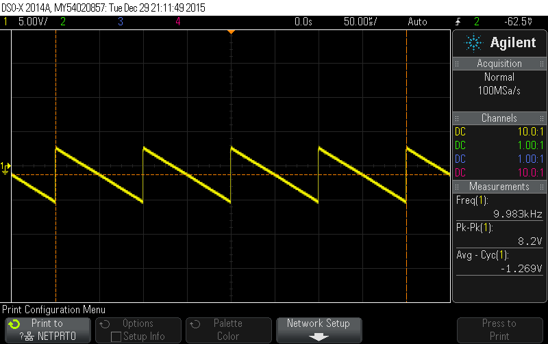
    • The oscilloscope capture of the input to U1A (after the filter) when the input is a constant 0V and when the ramp signal is applied

    Best regards,

    Ian Williams
    Linear Applications Engineer
    Precision Analog - Op Amps

  • Circuit used to produce the issue:

    Generator output impedance: 50‎Ω. Total input impedance: 1.05kΩ (I added the 1k resistor thinking that the RC low-pass at the input was required - though at 1.6MHz it doesn't do much).

    Output (with signal and without):

    Input (with signal and without):

  • Hello Olivier,

    Thank you for providing the requested information. I don't see any issues with the schematic.

    In the bottom two scope captures showing the input, it's clear than an offset of approximately -1.3V is present, even at DC. The output shows an offset of roughly twice the input, which lends me to believe that the issue does not lie with the amplifier.

    If you remove the OPA1642 from the PCB, does the signal after the filter still look the same, with the -1.3V offset? What kind of capacitor are you using for the 10uF coupling cap? In TIPD186 I used a ceramic, 35V rated, 10% tolerance X7R.

    Best regards,

    Ian Williams

  • Thanks for your reply! I'll try removing the op-amp tomorrow. The capacitor is 10µF, 35V, X5R (Murata GRM319R6YA106KA12D).

  • Removing power from the op-amp makes the offset disappear. And so does removing the op-amp.

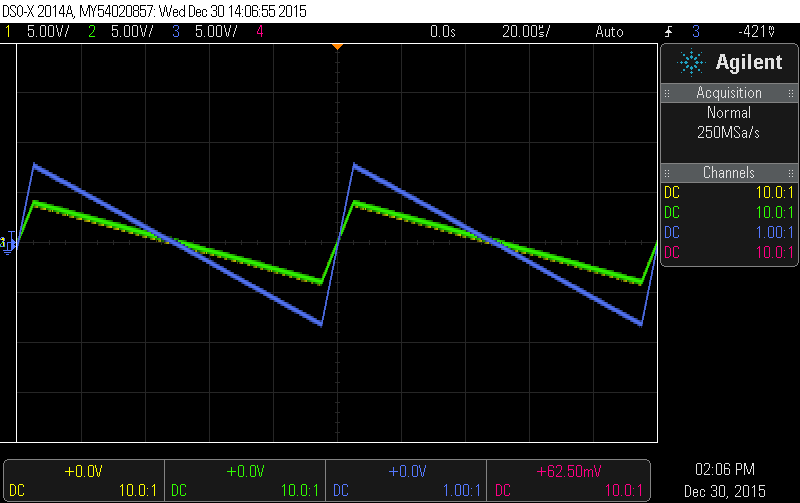
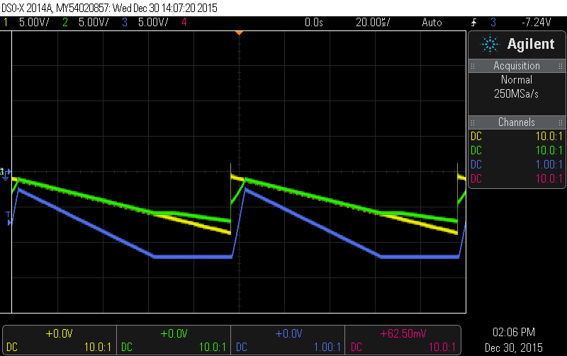
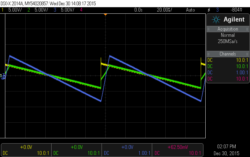
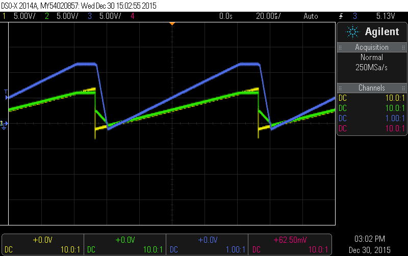
    I rebuilt a similar circuit with the (slower) OPA2171 this time, which illustrates more clearly what happens with fast edges.

    • Channel 1 (yellow) = op-amp V+ (post high-pass filter)
    • Channel 2 (green) = op-amp V- (middle point of the voltage divider)
    • Channel 3 (blue) = op-amp output.

    First, 8V pp, 0V DC, 10kHz ramp with 10% symmetry:

    All good.

    Changing the symmetry to 0% introduces a DC offset:

    Instead, I would expect:

    (Which is what I get when the input capacitor is shorted).

    With a reverse ramp, the opposite occurs:

    If we leave the circuit as is, we have to rely on the input signal to be "soft" enough (or the source impedance to be high enough to work with the 68pF cap at the input to soften the hard edges). This is not an unreasonable assumption for audio, but I've seen synthesizer modules output very brutal edges.

  • Hello Olivier,

    We are working on a thorough analysis of this phenomenon. You can expect a report on Monday the 4th, as we'll be out for New Year's Day.

    Best regards,

    Ian Williams

  • Oliver,

    The root cause of the issue is that back-to-back input  protection diodes turn on during the fast edge of the saw tooth waveform.  When they turn on, the input coupling capacitor is charged.  Fortunately, some amplifiers do not have the input diodes.  These amplifiers will not have the issue that you see.  We will provide you with some recommended parts from our marketing team.  Attached is an analysis that shows simulation and measured results with and without the input diodes.  In the case without the diodes it is clear that the issue does not occur.

    Note that I delayed sending this response as I had to check the OPA1642 in this configuration.   The OPA1642 does not have back-to-back diodes, so I would not have expected you to have the issue that you identified.  I tested the circuit with the OPA1642 and did not see the problem.  Can you please confirm that you were using the OPA1642 and not another device?

    input diodes for ac coupled circuiits.pdf

  • I observed a DC-offset issue with the original OPA1642 circuit and managed to reproduce a similar phenomenon with other parts, which led me to think it was a more salient instance of the same problem. I'll troubleshoot the original OPA1642 board and get back to you.

    Could you please let me know which, among these parts I commonly use, have the protection diodes?

    TL07x, LM324/LM358, OPA164x, OPA165x, LME497x0, OPAx134, OPAx171

  • Oliver,

    Here is the answer to your question regarding back-to-back input protection diodes:

    TL07x - No, it does NOT have the diodes

    LM324 - No

    LM358 - No

    OPA164x - No

    OPA165x - Yes, it DOES have the diodes

    OPA166x - Yes

    LME49710 - Yes

    OPAx134 - No

    OPAx171 - Yes

    OPAx192 - No

  • Thanks a lot for this precious piece of information!

    I have rebuilt another board with the OPA1642 and did not observe the issue - so I suspect the part might have been damaged on the original board, or that a construction error added parasitic impedance between Vs- and V+.