This thread has been locked.

If you have a related question, please click the "Ask a related question" button in the top right corner. The newly created question will be automatically linked to this question.

OPA4227 operating temperature and thermal-couple effects

Other Parts Discussed in Thread: OPA4227, OPA4188

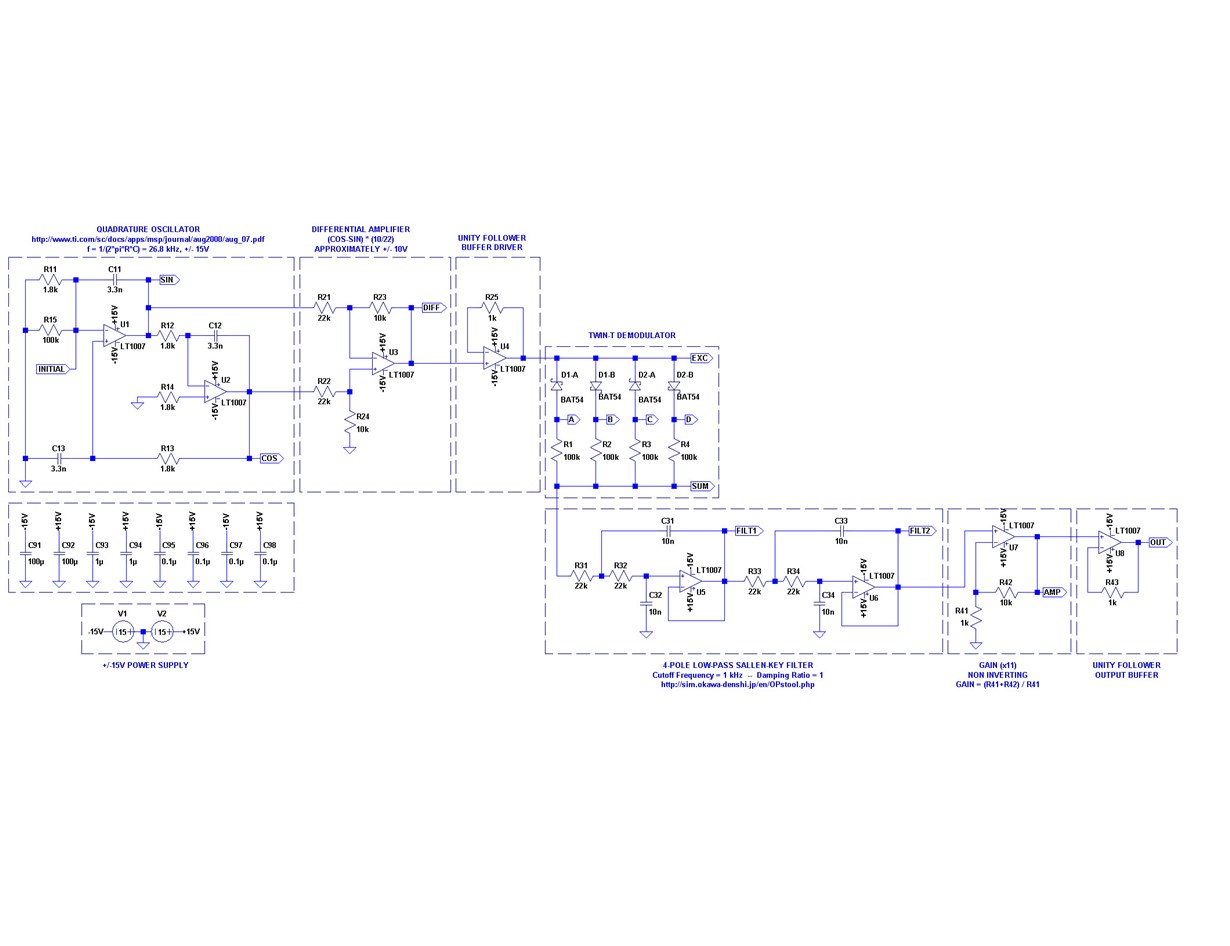
We designed a circuit using two OPA4227 chips powered at +/- 15 V. The circuit diagram is as attached (U1-U4: OPA1, U5-U8: OPA2). We found both chips generated a lot of heat which caused significant drifts in voltage output (OUT). We measured the surface temperature on both chips, which is ranging from 95 - 105 Deg F. Output voltage seems to strongly be correlated to chip temperature variations. 

Here are our questions:

  1. What's the normal operating temperature for the chip at +/- 15V.
  2. Do you see any obvious problems with circuit design?
  3. How to investigate for thermocouple effects if you think we might have that?

Thanks for your assistance!

  • Hello Jwan,

    Each op amp internal to the OPA4227 typically draws about 3.8 mA of current, or 15.2 mA for all four. Using +/-15 V supplies, or 30 V total, the power dissipation PD would be 0.456 W. If we want to estimate the package temperature (Tc) we need the junction-to-case thermal resistance θjc, which isn't listed in the datasheet. Using a TI thermal database I find it lists the θjc for the 14-pin SOIC package as 34.5 °C/W. Then, using an ambient temperature (TA) of 25 °C, the Tc can be calculated:

    Tc = TA + PD θjc = 25 °C + (0.456 W)(34.5 °C/W) = 40.7 °C

    Much cooler than 95 to 105 °C. Thus, it is clear that the OPA4227 is drawing much more current than the quiescent level, dissipating more power, and getting hotter than expected.

    When an op amp gets excessively hot, then something more than the expected is happening in the circuit. A common cause of excessive op amp operating current and overheating is caused by high frequency oscillation. Checking for oscillation with an O-scope equipped with a 10x probe is a good method for determining if oscillation is present. The output of each op amp should be checked for oscillation with the scope.

    Two of the OPA4227 op amp sections, U4 and U8, are connected as unity gain buffers. These stages would be most suspect for oscillation. And the fact that a 10 k resistor has been added in their feedback path increases their likelihood of oscillation. That is because the resistor, in conjunction with the op amp input  capacitance, adds a pole in the feedback loop and that reduces the phase margin and sets up the conditions required for oscillation.

    My recommendation is you check the circuit for high frequency oscillations. If found, then replace the 10 k feedback resistors with 0-Ohm shorts. Then, check the circuit again for over-heating and oscillation.

    Regards, Thomas

    PA - Linear Applications Engineering

  • Thank you for your response. I think probably op amp overheat might not be the issue, as I was talking about 95 to 105 °F, not 95 to 105 °C. So the temperature seems to be close to what you calculated. Our issue is we find strong correlations between chip temperature and circuit output. Could you please help to investigate the circuit and suggest how to reduce the thermocouple effects? Thanks!
  • Hi Jwan,

    Thank you for the correction regarding the temperature units; most often we are dealing with Celsius temperatures, and not Fahrenheit so I overlooked that point. Even if the temperature is in the expected range, I do suggest you check the circuit for high frequency oscillation. The point I made about the potential for the buffer stage to oscillate is valid. If oscillation is present, then that would corrupt the circuit's electrical performances and might be interpreted as some other problem with the circuit.

    Thermocouple effects are not commonly detectable in most op amp circuits because other thermal effects such as voltage offset drift, dVOS/dT are much larger and swamp their effect out. The only time that we have been able to observe thermocouple effects is in very low voltage offset, extremely low input bias current op amps in controlled environments. They were observed as contributing micro-volt level voltage offset that occurred when a temperature stream was blown across the devices and PC board on which they were mounted. The thermocouples were formed by the lead/solder/trace interfaces and are due to the dissimilar metals and temperature gradients developed across them. Their development is unavoidable unless the same metal system is used for everything. And then, there is the thermocouples inside the IC package formed where the lead-frame, bond wires and IC metal connect. Those are unavoidable. 

    One of my Applications Engineering colleagues set out to determined just how much of an issue thermocouples are in an analog circuit. He devised some test circuits where thermocouples were intentionally created on a PC board and set off to measure there effectiveness. A TI Tech Day session that includes his thermocouple work is attached. See pages 7 through 20 of the session, and the presenter's notes for explanations of the slides.

    It might be that there is a thermocouple issue with your design, but I expect that the voltage offset drift of the op amps is a larger source of error. If that is the case, then you may need to employ a chopper type op amp such as the OPA4188 in your application to minimize drift effects.

    Regards, Thomas

    PA - Linear Applications

    Parasitics in Precision PCB Layouts_Ian Williams.pptx