This thread has been locked.

If you have a related question, please click the "Ask a related question" button in the top right corner. The newly created question will be automatically linked to this question.

Lm258 non-linear behaviour in differential amplifier configuration

Other Parts Discussed in Thread: LM258, LM7322

Hi,

I am using LM258 in a differential amplifier configuration as a high side current sensing with the gain of approx. 56 with resistor gain of 332k ohms and 5k9 ohms. The opamp is supplied with 24V and the common mode voltage is sitting approximately at 16V as shown in the schematic attached:

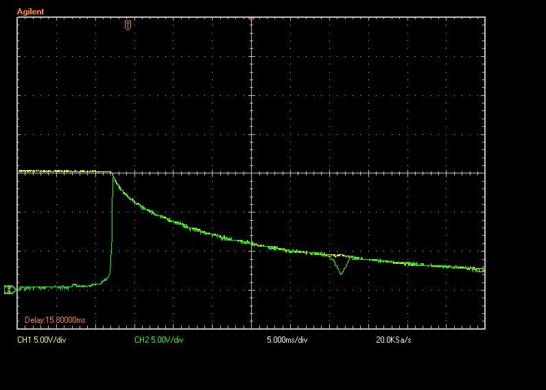
I am having a non linear behaviour with the circuit as the supply voltage drops at the power supply turn off. The following is measured on the bench at room temperature.

The output of the opamp is approx. 40mV when there is no load and the supply voltage is >16V (Common mode input range parameter is being satisfied; 0 to Vcc-1.5V). As the supply to the opamp drops to ~16V, the output of the opamp jumps from ~40mV to ~17V following the supply voltage minus ~0.6V from the transistor drop. 

I measured some voltages around the circuit. During the normal operation, the non inverting terminal is approx. 15.288V and the inverting terminal is approx. 15.300V (i.e. the voltages are close to each other). 

As the supply voltage drops (and the common mode input range is violated), the non inverting terminal is approx. 15.355V and the inverting terminal goes to 15.635V, and the output goes to 14.780V!

I understand that as I am violating the common mode input range in the opamp the opamp is not operating linearly but what I don't understand is why the output jumps from 40mV to 14V. The simulation with SPICE does not indicate this issue and I don't expect to as this is the non linear behaviour of the opamp.

Has anyone encounter this behaviour before or have explanation as to why this happens?

Thanks

Samuel

  • Samuel,

    When both inputs exceed upper common mode range the input PNP transistor cut off. Once this happen the device is no longer controlled bu the inputs and the device it will its own thing. Usually the output goes high, but it is also possible that it would go low. 

  • Samuel,

    Spice model show normal behavior well but out of range results don't always simulate correctly.
  • Hi Ron,


    Thanks for your reply. I understand that the non-linear behaviour of an op-amp cannot be simulated correctly/ explained easily. Like you said, the opamp output did go high in this case.

    I imagine the correct way to solve this issue is to ensure that the common mode voltage goes down at the same time as the supply voltage to the opamp and ensure that the common mode range is never violated.

    Thanks

    Samuel

  • Samuel,

    That could work or you could could detect that 24V supply is incorrect and mask the output as invalid or flag a error that overrides the current measurement error.

    I suspect that you are getting an error signal during power down that is causing a problem.

  • Hi Ron,


    Yes, you are right. The problem appears during power down. As the supply of the opamp drops, the common terminal is still at the same level (~15V). The concern that I have is that during the shutdown, the output shoots to 14V and that output is connected to an ADC pin. There is a protection diode to the 3V3 rail and there is a 3.6V zener that clamps the voltage to approx. 3.8V (given the range of the zener).

    The concern is that voltage is still being seen by the ADC that may cause an issue over time. I will have to think of other way to disable the 15V regulator at the same time or before the supply drops to a certain voltage.

    Would it helps if I used different opamp for this circuit?

    Thanks for your help Ron

    Samuel

  • Samuel,

    Another op amp could work, but I haven't seen any data sheets that guarantee an low output low when common mode range is exceeded.
    Could you add an open collector/drain comparator output to the LM258 non inverting input that could pull it low when 24V is falling?
  • Hi Ron,


    Thanks for your reply. I managed to control the terminal voltage by shutting down the 15V regulator around 22V input (i.e. when supply to LM258 is 22V, the 15V regulator has been shut off). However, I still have the same problem where the output still goes high, mimicking the 15V rail even though the supply is higher.

    Attached scope plot shows the behaviour:

    CH3 (purple) is scoped at the output of LM258. If you look at the time when the output jumps high, the supply voltage is approx. 20V (CH4 - dark blue) and the 15V rail is approx. 14.8V (CH1 - yellow).

    Here is another scope plot of showing the same behaviour of the opamp:

    CH1-yellow is 15V the input terminal voltage; CH2 - light blue is Vin to the board; CH3 - purple is opamp's output; CH4-dark blue is opamp supply
    All 4 plots on the same offset. As you can see the supply is higher than the input terminal voltage but the opamp output still goes high, following the input terminal voltage.

    I also tried rail-to-rail opamp that can handle the common mode voltage, LM7322 and supply it with the same terminal voltage (i.e. 15V rail) but the issue still persists:

    CH1-Yellow (15V rail: opamp supply and terminal voltage), CH2 - Green (opamp's output).

    This makes me wonder that the issue is something else than the common mode input range, which was thought to be the issue initially. Would you have any idea on where to debug?

    Regards

    Samuel

  • Samuel,

    The output seems to go high a little sooner than I would expect. However, I don't think any new effect is happening.
    Because the high pulse is shorter, I think you are getting closer to a solution.
  • Hi Ron,

    I have found the problem: it was a capacitor!! placed after the sense resistor.

    The capacitor causes a lag on the inverting terminal as the power is shutdown, causes positive difference between the input terminals. This difference gets amplified with high gain of the opamp (~50) but limited by the opamp supply.

    As soon as I remove the capacitor, the problem is not present.

    Thanks for your help,

    Samuel