This thread has been locked.

If you have a related question, please click the "Ask a related question" button in the top right corner. The newly created question will be automatically linked to this question.

DRV421EVM functionality problem

Other Parts Discussed in Thread: DRV421EVM, DRV421

Hi,

I observed two problems during testing of DRV421EVM.

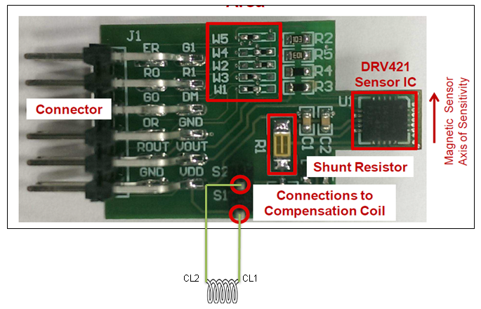
1) As shown in below figure if I connect let say S2 (in kit) to CL2 (compensation coil over core) and S1 to CL1, board takes 10mA while on interchanging compensation coil connection that is S2 to CL1 and S1 to CL2 board takes ~70mA (limited to < 70mA due to 10 ohm sense resistor and 65 ohm compensation coil resistance at 5VDD).  There was some remanence in core so I even tried degauss option, it works with S1-CL1 & S2-CL2 combination but on reversing that is S1-CL2 & S2-CL1 (when board takes 70mA) it doesn’t work. And in 70mA consumption case OR (over range) pin voltage is low indicating saturation.

Can anyone please explain why compensation coil connection reversal is making abnormal behavior ?

2) Assuming there could be problem with IC  in above case I replaced the IC but it did not perform in the beginning and then started performing after few minutes. It seems it got hanged. Later on repetition of above case same behavior observed. 

  • Hi Ankit,

    Thanks for your question. I will forward this question to our DRV expert and will get answers to you ASAP. He is on business travel so please allow him some time for review.
  • When current passes through the core, the change in flux is sensed by the DRV421. The DRV421 applies current to the compensation coil in order to bring the flux back to zero. In the case of when the coil winding was interchanged, instead of reducing the flux in the core to zero, the flux was being amplified by the DRV421. The drive stage will saturate and draw high current just as you described. You can get the same effect if you rotate the DRV421 180 degrees in the core without changing the compensation coils leads.

    On Q2, I suspect that was perhaps a soldering issue. We have never seen the part 'hang' for 10 minutes and then begin to work.

    Regards,
    Javier

  • Hi Javier,

    Thanks for you answer...
    If this is the case then is this specified in datasheet to connect compensation coil in particular fashion or it has to be checked by testing ?
    When I connect the compensation coil in right direction where DRV421 is not saturating and pass DC current carrying wire through core gap then even on reversing current direction through core gap it gives correct output.
    Also I see H-bridge driver inside DRV421, since this is close loop IC I think it should change the direction of H-bridge switches to make flux zero. So even if compensation coil connected in any order due to close loop sensing it can turn ON H-bridge switches in a way to make flux zero.

    Why on reversing the sense current direction passed through core gap it works while on reversing compensation coil connection it doesn't?

    Thanks&Regards.
    Ankit
  • Hi Javier,

    At least I found in datasheet that compensation coil polarity in important in para 7.3.3 of datasheet.
    Still if you can put some thought on last asked query it will helpful.

    Thanks&Regards,
    Ankit
  • Hi Ankit,

    The easiest way to explain this is like an op-amp in a feedback loop. The amplifier needs a negative feedback to function correctly, even though it can force voltages high and low and source and sink current.

    There are a few things that matter in this like the direction of the coil rotation, and the field sensitivity direction of the part. It is much easier to just switch the connection of the compensation coil or rotate the DRV421 180 degrees in your setup to get the correct orientation.

    Hope this makes thing a little clearer.

    Regards,
    Javier
  • Thanks Javier...Got your point.

    Regards,

    Ankit