A related question is a question created from another question. When the related question is created, it will be automatically linked to the original question.
If you have a related question, please click the "Ask a related question" button in the top right corner. The newly created question will be automatically linked to this question.
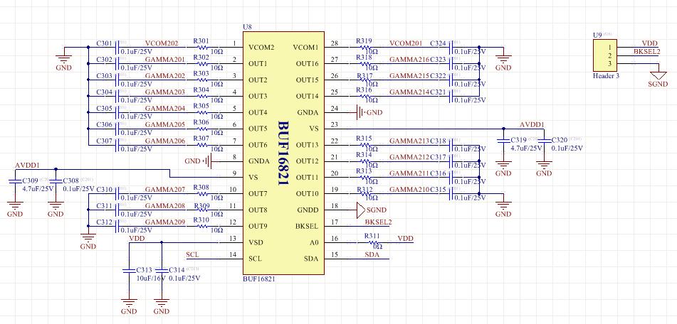
Below is the BUF16821's circuit, can someone have a advise for the filter capacitor that where it should be connected to the power ground or signal ground?
And the circuit need to be modified if any?Thanks ~
The analog and digital ground connections of the BUF16821 must be connected together, as specified in the data sheet.
As for decoupling capacitors on the power supplies, we recommend copying what's on the BUF16821EVM-USB User's Guide:
4.7uF and 1uF bulk decoupling capacitors between each supply and GND, placed at the power connectors on the PCB
0.1uF local decoupling capacitors from each power pin (Vs - pin 9, Vs - pin 23, Vsd - pin 13) to GND, placed as close to the BUF16821 as possible
We do not recommend placing a filter RC network at the output of our gamma buffer devices, as they can exacerbate stability issues and make the device more susceptible to EOS (electrical overstress) events. If the BUF16821 will be driving a large capacitive load, a series resistance at each output such as 10 or 100 ohms may be helpful, but we don't recommend placing a 0.1uF capacitor at each output.
Best regards,
Ian Williams Linear Applications Engineer Precision Analog - Op Amps