Other Parts Discussed in Thread: THS4131
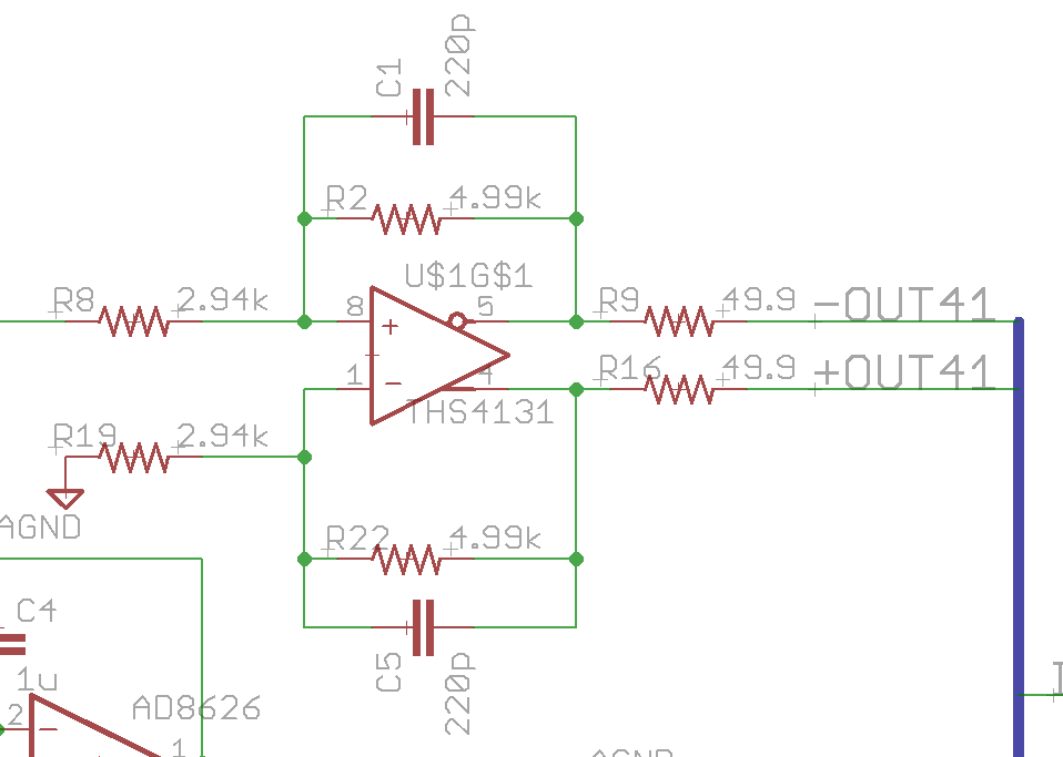
Hello. I'm using the THS4131 as a single-ended to differential converter at the output of an amplifier circuit. I've pasted a portion of the circuit schematic relevant to this discussion below.
The configuration is similar to Figure 38 of the datasheet, with a capacitor in parallel with each Rf to get a single-pole low-pass filter.
Using a 220pF capacitor and Rf=4.99k, I calculate a cutoff frequency around 140kHz (fc=1/(2*PI*Rf*Cf). I confirmed the cutoff in simulation using LTSpice prior to PCB fab.
The problem is this - in test I measure a cutoff frequency in the 90kHz range (equivalent to a 320pF capacitor). The PCB has 10 channels and they are all consistent. I verified the proper components were purchased and installed. I also confirmed the stage preceding the THS4131 has a wider bandwidth - i.e. the THS4131 is the bandwidth-limiting stage.
Regarding the layout, I'm using a 10-layer board, 0.063" thick. I followed the layout guidelines in the datasheet except I left the ground plane underneath the part pins, and added a ground pad underneath the part body for thermal reasons. I can see how this would add 10s of pF, but not 100pF (unless I'm missing something). The PCB is straight from the assembly house so it's reasonably clean.
I can experimentally figure out the new capacitance needed to get a bandwidth of 140kHz, but I'm not quite clear why these values result in a bandwidth much lower than expected. Any ideas?
It's worth mentioning the load during bandwidth measurements was a high-impedance oscope channel, with coax length <6ft.
Thanks!
Josh