This thread has been locked.

If you have a related question, please click the "Ask a related question" button in the top right corner. The newly created question will be automatically linked to this question.

PGA281 slew rate limitation

Other Parts Discussed in Thread: PGA281, PGA280

Hi all,

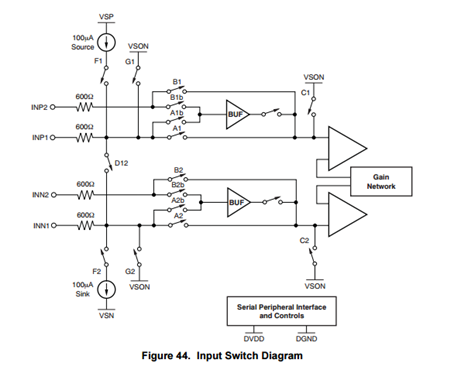
one of my assigned account is using the PGA281 to attenuate signals which belongs from a multiplexer.

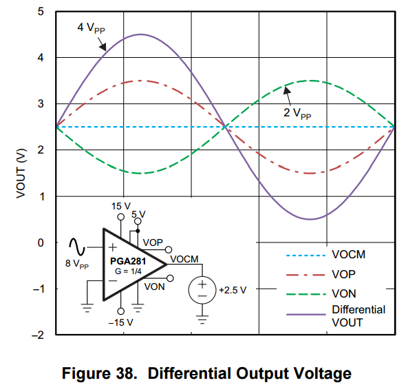
The PGA is supplied at +/-15V, the output stage is supplied between 0 (-150mV)  and 5V. The VOCM is set at 500mV. The output is used in single ended.

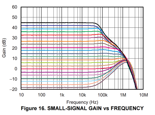
Often the PGA281 goes in error (slew rate limitation) during the switching from one channel to another of the MUX. It happens because the signals are very different from each other and the slew rate limitation is easily reached.

The customer in theory could even survive wiht this issue, but the side effect is that the PGA281 takes some time to exit from the error condition. and in that time a lot of current is sunk from the source.

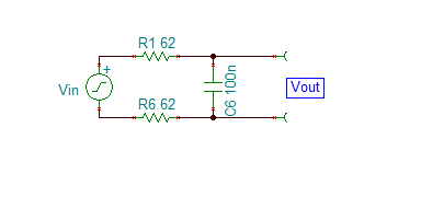
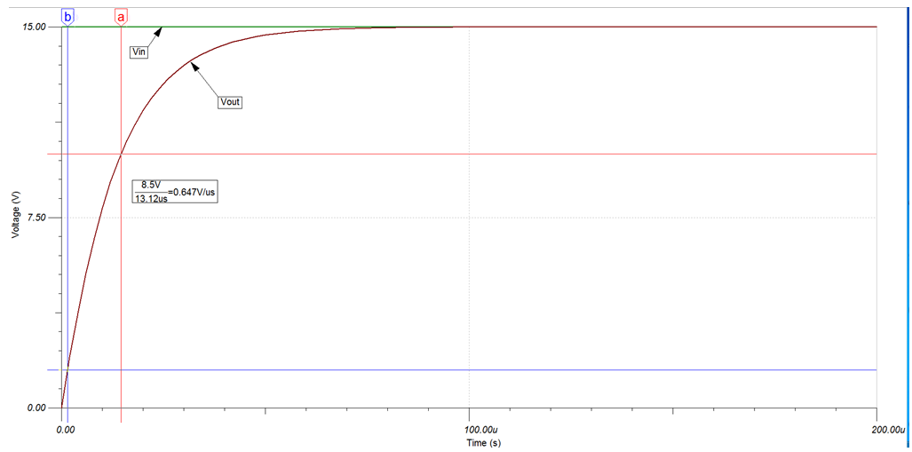
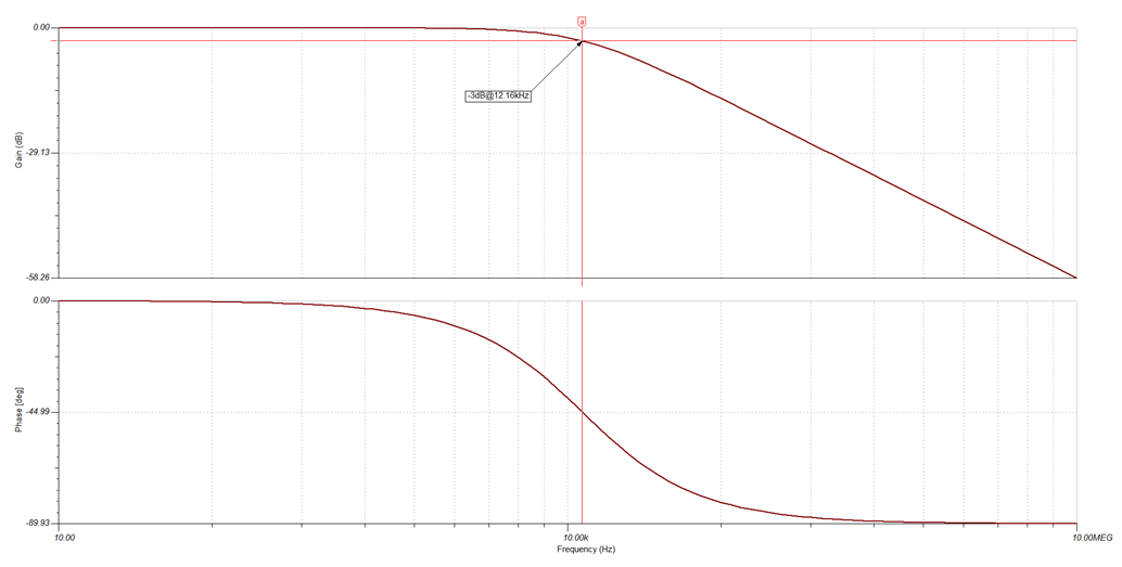
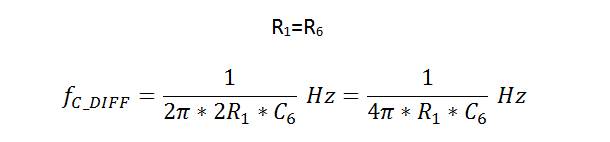
 The customer would avoid extra op amp to reduce the SR. I'm thinking to some RC input filter. Can you suggest any workaround to limit this side effect ?

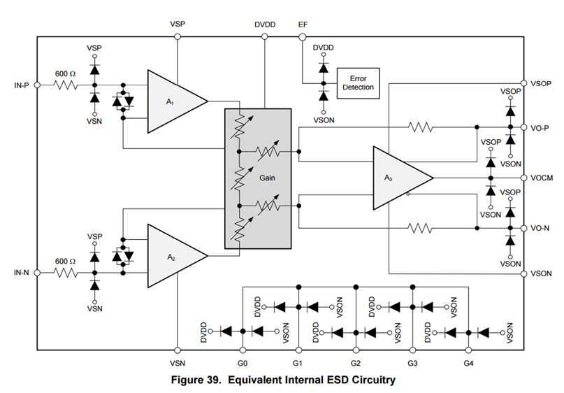
Could a series resistence at the input pins of the PGA281 in conjuction with its input capacitance limit the SR of the signal and mitigate the current sunk by the source ?

The customer is also interested to know if this continuing permanence in Error could damage the PGA281. What do you think ?

regards,

Domenico

  • Hello Domenico,

    This is to be expected when using an external MUX switching with the PGA281. One option would be to use the PGA280 which has a pair of high-speed current buffers that can be activated to avoid inrush currents during fast signal transients, such as those generated from switching the signal multiplexers. This feature minimizes discharge errors in passive signal input filters in front of the multiplexer.


    Another alternative would be to an RC filter network with the values below. The small signal gain vs. frequency plot below usable bandwidth across multiple gains.  The usable bandwidth across all gains is 10kHz, the pole for the filter would have to set a decade away from the bandwidth (at 100kHz). 


    Taking into consideration the slew rate of the device, the filter example below was based off a unit step of 15V that would stay with the slew rate of 1V/us of the PGA281.

    Filter Network:

     Transient Step Response:


    This reduces the bandwidth to 12.16kHz.


    The cutoff frequency of the filter defined below:


    What is the frequency and peak-to-peak of the signals going into PGA280?

    For the damage concerns based the PGA281 has internal resistors of 600ohms to limit the current. So the part will not be damaged by this event.  


    Best,


    Errol Leon

    Texas Instruments

    Op-Amp Applications

  • Hi Errol,
    thanks for the explanation.

    The signals handled by the customer are very slow, they are pressure and/or temperature information. The limitation of the SR has you highlighted ws related essentially during the switching of the channels.

    For future design whith higher BW signlas I'll suggest the PGA280.

    Just one more thing, the customer is using the device in signle ended output, he is using the VO-P output only. Due to low VOCM set, the VO-N output reaches the rails and so the EF is high. The quality of the output signal even in single ended is good for the customer, does the EF high introduce any side effect ?

    thanks,
    Domenico
  • Hi Domenico,

    The internal error detection in the input and output stage monitors signal integrity and provides a logic information about the input signal condition on the EF pin output.  Since it is a logic OR indicator, it will not introduce any side effects, however, if the EF is indicating an error (logic high) the circuit is in an undesirable condition.  In this case, the error flag (EF pin) alarm indicates a loss of performance as a result of the amplifier output approaching the rail.  This is a result of VOCM being set low (500mV).  Since this device is being used for a single-ended application the set gain is divided by 1/2.  To achieve a wider range swing and not approach the rail and possibly cause an EF error, VOCM is recommended to be at 2.5V.

    Best,

    Errol