This thread has been locked.

If you have a related question, please click the "Ask a related question" button in the top right corner. The newly created question will be automatically linked to this question.

THS4631: ALTERNATIVE TRANSIMPEDANCE CONFIGURATIONS

Part Number: THS4631
Other Parts Discussed in Thread: OPA857, OPA842, TINA-TI

Hello,

I want to use THS4631 for photodiode amplifier, and since i need to use a very low feedback capacitor, I am implementing Figure 39. Alternative Transimpedence Configuration 1 from the THS4631 datasheet. However, when I tried to simulate it on LTSpice, its results is not stable. From my guess, I think I chose the wrong Cf (Feedback Capacitor).

I want to clarify:

1. The Rf value in the Cf equation is Rf2 and the gain should be Rf1 + Rf2

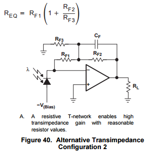
2. In this case, I found it the Req is not correct. Simple analysis, if I make the Rf3 open (inf resistance) the Req becomes Rf1 only. Hence, the gain should be: (Rf1Rf2 + Rf1Rf3 + Rf2Rf3)/Rf3

Thanks,

  • Hello,
    The value of Req shown in equation 5, is correct. That is the value of your low frequency transimpedance gain. Because of the difference in circuit architecture however, Equation (1) may not be able to be used directly. Can you please let me know the value of each resistor you are using as well as your photodiode capacitance.

    -Samir
  • I want to use Figure 39 for my design. So my input signal will be a sine signal with f=10mHz and 1pf cap.
    And I want the gain to be 10 000, so I chose rf1=rf2=5000ohm. However, I did not know how to calculate the Cf correctly because the simulation gave me an unstable result. Can you provide me a good approach how can I solve the Equation 1?

    Thanks,
  • Hello,

    10kohm is not a very large resistor. I would just use a straight 10kOhm resistor. A better solution for you is to look at the integrated TIA - the OPA857, that amplifier can provide a gain of 20 kOhm and a bandwidth of 100 MHz.

    Also, at 10 kOhm I would probably use an amplifier with BJT inputs like the OPA842. See this app note for when to use JFET/CMOS and when to use BJT from a noise perspective.

    http://www.ti.com/lit/an/sboa122/sboa122.pdf

    BTW can you please confirm if 10mHz is milli-Hertz or Mega-Hertz.

    -Samir

  • I might want to increase the gain by an order of magnitude. Can you give me an accurate Cf calculation (formula) for 1pf and 10 meghahertz input signal? The Cf value is so low, that's why I want to use the alternative configuration.
    I will try to simulate the OPA842.
    Thanks,

  • Hello,

    Please consult these two blog posts to figure out how to compensate a standard  TIA circuit-

    e2e.ti.com/.../what-you-need-to-know-about-transimpedance-amplifiers-part-1

    e2e.ti.com/.../what-you-need-to-know-about-transimpedance-amplifiers-part-2

    There is a link to a calculator there that you can use to find a solution. If you need a solution to the modified circuit, you will have to work the math out or simulate this in TINA-TI or your simulator of choice. To determine the appropriate Cf you will need to simulate the loop gain and determine the amount of phase margin you need.

    Looking at your circuit above I am not quite sure what you are trying to do. If your source is a photodiode that is modeled as a current source with a shunt capacitor. Looks like you have a voltage source with a series capacitor. Again if you follow the blog posts you will see how to simulate a TIA circuit for loop gain and frequency response.

    -Samir