


Other Parts Discussed in Thread: OPA365
Hello,
I am designing an attenuator and follower stage for voltage measurements. I have designed the voltage divider to do a divide by 20 function. The max amplitude that I will see is 20V. Therefore, this would bring my voltage into the range of 1V for my ADC. During my design process, I read that it is important to introduce a capacitive divider to "even-out" the frequency response of the circuit at higher frequencies.
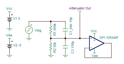
Figure 1: The circuit concept
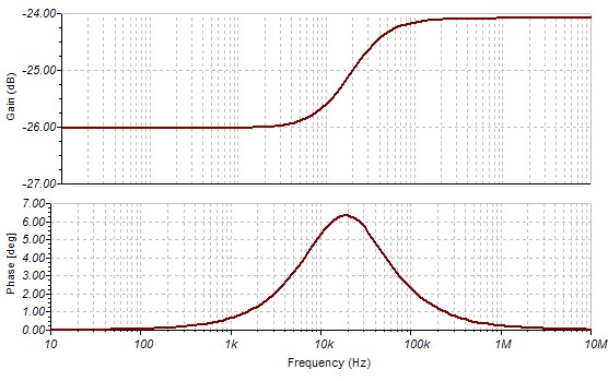
Figure 2: The associated frequency response
My issue is that I can't figure out how the capacitor values are related and how they affect the resistors. This frequency response here indicates some kind of obvious RC filtering going on. What I want to do is provide the input with about 25 pF of capacitance, and also obtain a minimum bandwidth of 1MHz.
Is there something that the simulation is not showing me? Or is there some "real-life" constraint that I need to be wary of?
Thanks,
Alex

