This thread has been locked.

If you have a related question, please click the "Ask a related question" button in the top right corner. The newly created question will be automatically linked to this question.

TLV2172: There is an short path in the DC-fan control circuit with TLV2172.

Part Number: TLV2172

Hi All.

I've made DC-fan control circuit with TLV2172, and faced with very extraordinary situation which hidden short path exist in the circuit. It seems to me that the root cause is PCB pattern, but I don't have any nice idea how I can debug it. Could you check my explanation about the failure, and let me know if you have any good idea to solve this problem?

A sequence to the failure is as following:

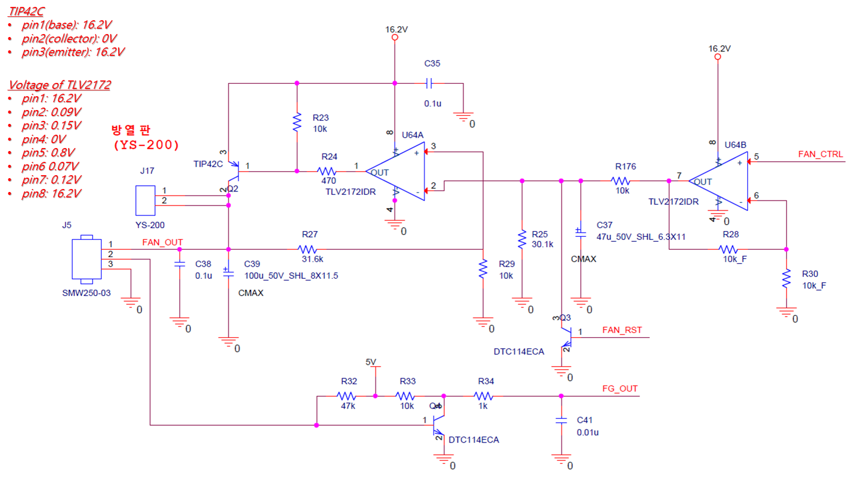
  1. At first, as no DC-fan is connected, the voltages shown in TLV2172 and TIP42C are described in the diagram as attached. It really doesn't make sense.
  2. Second, as DC-fan is connected, surprisingly short path occurs and the supply voltage of 16.2V to the emiiter is disappeared, however I really don't have any idea where this short path exist.
  3. Third, as DC-fan is connected, I limited the current from DC power supply to 300mA, and started to increase supply voltage to emitter from 0V to 16.2V. As the supply voltage surpass 1V, the short circuit occurs and current start to increase.

For your reference,

  1. Thevenin resistance of DC-Fan is 300 ohm.
  2. I've checked the TLV2172 separately (off the board), it works well. It works as correct amplifier.
  3. I've also checked the TIP42C separately (off the board), it works as well like correct PNP transistor.

  • Kyutae,

    Using your voltage table, I see some problems.
    How can Collector be 0V and op amp pin 3 be 150mV at the same time?
    Pin 5 voltage is greater than pin 6, therefore pin 7 should go high.

    I also see some good voltages.
    Pin 2 is about 3/4 of pin 7
    PIn 6 is about 1/2 of pin 7
    Pin 3 is greater than pin 2, so output on pin 1 is high.
  • Hi Ron.

    Yes, you're right, however "this is the case!", and that's the reason why I call this situation extraordinary. On the top of your comments, as I simulated the circuit, 16.2V should be shown at collector of TIP42C in no load condition because base voltage is dropped to 15.35V due to leakage current of the OP amp, however collector voltage is 0V.

    The point I've been concerning is "Hidden Short Path" inside PCB. I've verified the circuit and its gerber file several times, but I didn't find any problems in them. No failure occurs as I tested TLV2172 and TIP42C separately (off the board), however the failure occurs just as it's mounted on the board.

    I've never experience this kind of error, so I have no idea how I could find the hidden short path in the circuit, and I really really really want to know how I should approach to this kind of failure. 

  • Hi Kyutae,

    Is the TIP42 on a heat-sink? For TO-220 packages, the tab is usually connected to the center pin (Collector!)

    Did you use an insulator between the tab (and screw) and the heatsink?

    Bolting the case down to a grounded heatsink will short the collector to ground. There is your collector to GND short!
  • Hi, Paul.

    The heatsink is connected to the collector of TIP42, and I've found the root cause of the short path. It's the oscillation in the TLV2172 due to floating voltage at pin 5. after adding pull-down resistor on the pin, the issue is solved.

    Here's my additional question. How can the oscillation occur in the op amp?

    I've tested it in two ways. One is on the PCB board in which all components including capacitors are populated, and another is on the bread-board in which only resister is used to simply configure the control circuit.  However, regardless of the existence of caps, similar oscillation occurs as attached below. Can you explain how can the oscillation occur in the op amp, and how can the similar oscillation occur with same frequency of 60Hz even without caps?

    #1. Test on the PCB board (Oscillation of half-sine wave with 60Hz freq.)

    #2. Test on the bread-board (Oscillation of square wave with 60Hz freq.)

  • If pin 7 has 60Hz signal then so does the input on pin 5. This could be a unshielded input pickup or a feedback loop from output maybe due to ground loops.

    I do expect pin 1 to oscillate but not at 60Hz. The transistor adds gain the the feedback loop. C39 provides lag. Both of these effects hurt phase margin. The usual solution is the add a capacitor from pin 1 to pin 2. However a series resistance needs to be added between pin 2 and R25 node. The [new R]and [new C] creates a high frequency bypass that has good phase margin.
  • Hi, Ron.
    Thanks for your comment.
    I have one more question on the 60Hz frequency for a clarification. Can you explain why or how 60Hz can happen in the circuit without any AC signal inputs and only with 16.2V Vcc to the op amps?

    Thanks and regards!
  • Kyuate,

    In your two oscilloscope pictures, what are the nodes tested for channels 1, 2, and M
  • Hi Ron. I used the channel 1 only for a measurement at pin 7. No use of channel 1 and M. M is an math operation with channel 1 and 2. Thanks.
  • Kyutae,

    Pin 7 is supposed to be twice the voltage present on pin 5 as the gain is +2.
    It seem pin 5 is floating and picks up the 60Hz in the air.