This thread has been locked.

If you have a related question, please click the "Ask a related question" button in the top right corner. The newly created question will be automatically linked to this question.

OPA2354: about the risk of OPA2354 application

Part Number: OPA2354

hi dear supporting team,

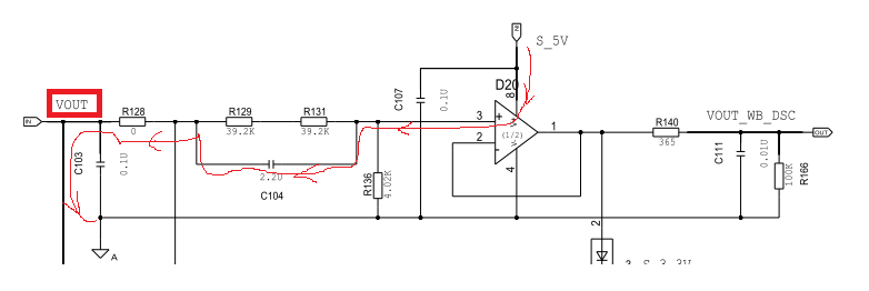
my customer is using OPA2354 in their power module, circuit as below:


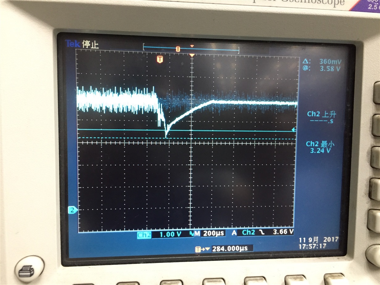
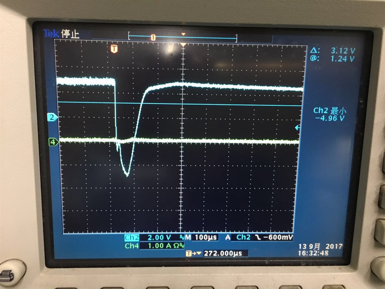
they need do short circuit experiment which will short the Vout poin in red circle below to GND for 1~2hours.  when they short the point,  they will find the power supply for OPA2354 will drop to ~1.5V, as below:  

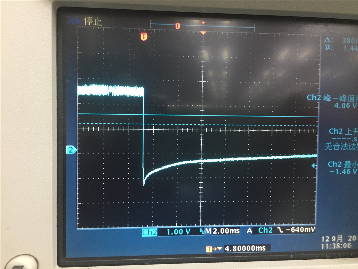
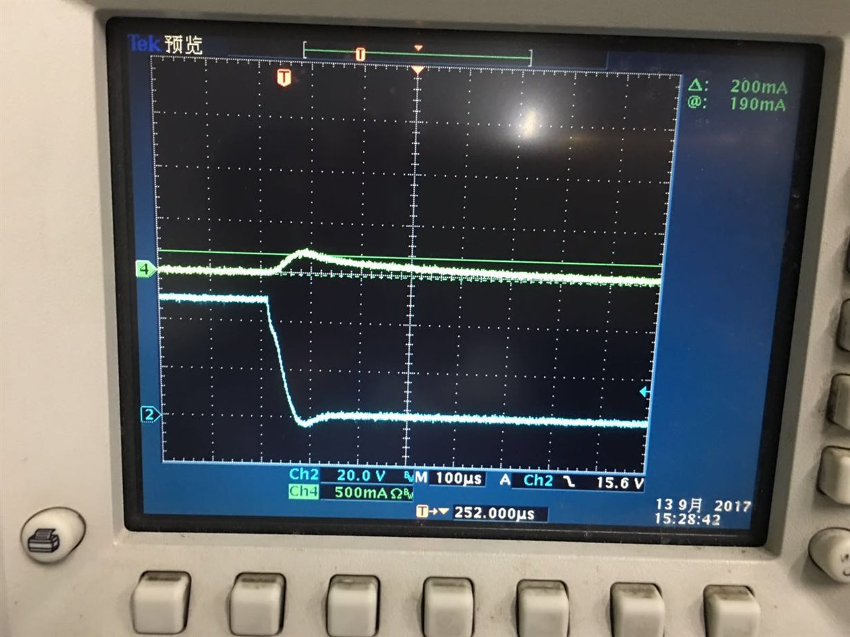
 and with R128=0, the PIN3 will be around -6V, and when they change R128 to 200 Ohm, PIN3 will get to around -1.5V. as below is the voltage test at PIN3 when change R128 to 200 Ohm.

if they remove the C104, and then the power supply will not dropped.  and also the PIN3 will not have negative voltage. but C104 could not be removed.

so need your support on below:

1.  what cause the drop of 5V supply?  customer thought there is a current pull loop which shown in the red.

2. because from the d/s, the minimum absolute voltage will be -0.5V with VCC-=0V.pls help evaluate whether there is any risk for such application.  so if it could, pls help suggest the solution.  (or do you need further information such as the current flow through the pin3 and etc to judge whether it could cause damage?) 

tks a lot~!

  • The issue is the voltage dropped across C104 immediately appears at pin-3 when Vout is grouned. During normal operation, left to right + - voltage is dropped across R129+R131 (i.e. across C104). When the left side of cap is suddenly shorted to gnd, the voltage across the cap immediately appears as negative voltage on pin-3.

    I noticed pin-3 is at 2.5V (second scope shot, I assume this is normal operation?). If Vout is where the voltage is forced to get 2.5V at pin-3 then based on the ~1/20 voltage divider formed by R129+R131 and 136 (assuming R128=0), Vout should be ~50V. Is this correct?

    In this case, ~47.5V will be dropped across C104.

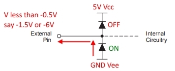
    If pin-3 has negative voltage with Vee=0V (GND), the internal ESD diode between pin-3 and Vee will turn on, pulling the current from GND instead of Vcc as you show.

    There are circuit elements that are not shown in the schematic image. It is possible the undesirable cap voltage effects I described earlier, along with current pull from GND maybe causing the supplies to drop. I noticed the supply goes back to 5V in 400 us while time constant on pin-3 is over 12 ms.

    You mention C104 could not be removed but is it possible to reduce the resistance (thereby voltage drop) in parallel with the capacitor?

    Thanks.

  • Hi Keyur,

    thank you for the support!

    yes, the VOUT is around 48~50V. 

    I did reduced the resistance in parallel with the cap, while still not get to the target, below is the detail result. 

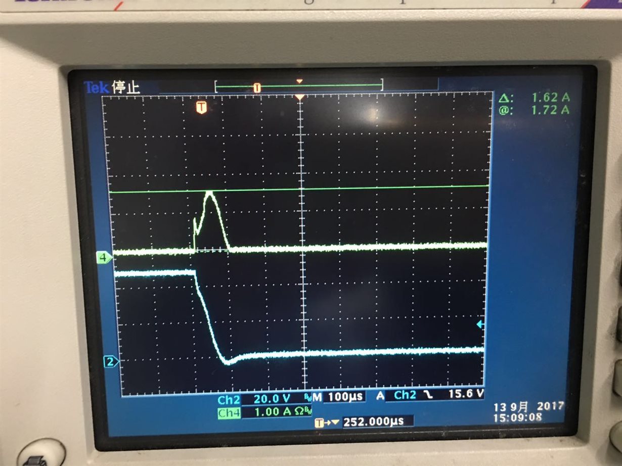
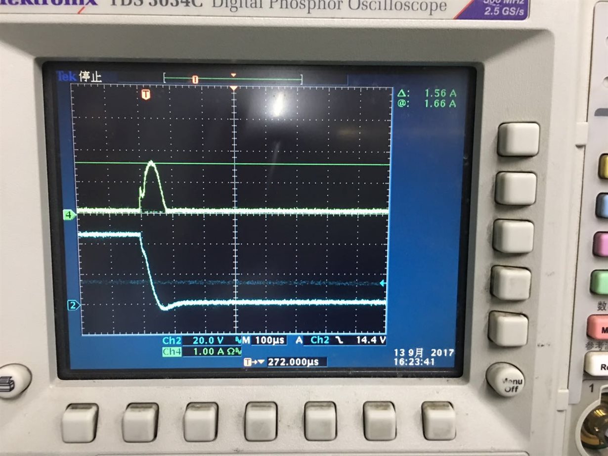
    1. with orginal setting,  R128=0 ohm,  we could get -6V peak voltage at PIN3 when doing shorting, the peak current flow through PIN3 when doing the shorting is 1.6A and last for around 100us. as below:

    2. with R128=200 ohm, other circuit keep the same,  PIN3 voltage will get to -1.5V when doing shorting.  and 200mA peak current last for around 200us. 

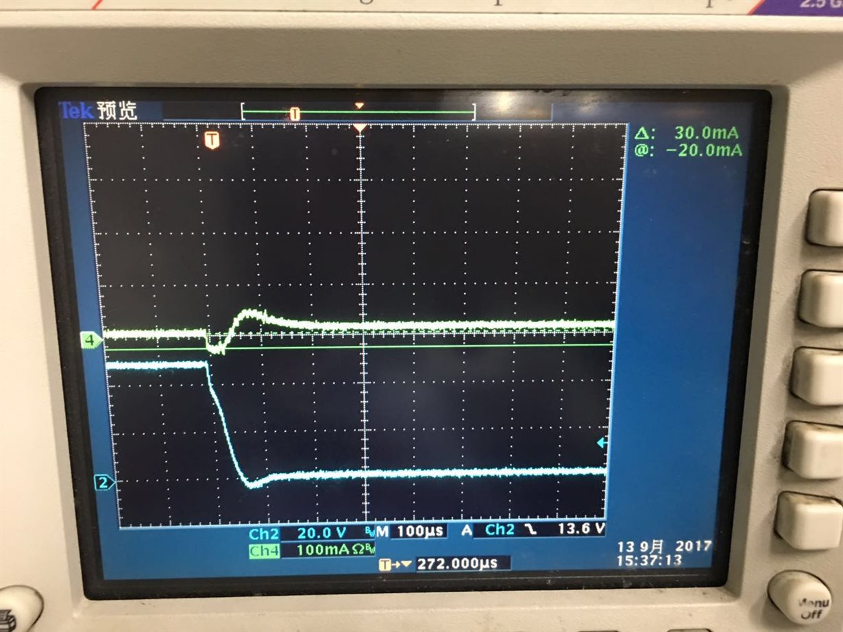
    3. with R128=3K, R127 reduced to 33k to keep the VOUT at 48V, PIN3 peak current will be 0.8V, and the current shown is like -30mA~-40mA.

    4. R128=0, R127=R131=30k, we adjust the s/w to keep output to 45V(can not be bigger),  and still get 1.6A peak current.   and around -6V at PIN3.

    I am now asking customer to keep tuning R127 to bigger to see whether it could be accept to their system. while still need your support on below items:

    1.  pls help check whether test case #2 &#3 will distroy the chip from long term application, i.e.  -1.5V with 200mA at PIN3, and -0.8V&40mA at Pin3.

    2. pls also share the rough input circuit of our chip,  including the diode you mentioned. is it for clamping or other function? 

    tks a lot!

  • Vera,

    There a lot of compounding effects happening with the capacitor in place when you try to short VOUT to GND - without the amplifier, the node at Pin3 wants to go much lower (whatever the voltage across C104) than -6V or -1.5V that you are seeing with R128 = 0 or 200. Only reason you are not seeing those voltages is because the ESD diodes inside OPA2354 are turning on. Without trying to analyze everything that you are seeing, what I can tell is that this is not a good situation for OPA2354.

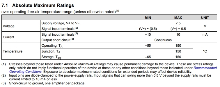
    1. Any of the cases you mention can cause permanent damage to the chip. See abs max ratings below. To avoid damage to the device in the application, there are two main conditions:

    a. Keep voltage on input terminals less than Vcc+0.5V and above Vee-0.5V i.e. between 5.5V and -0.5V in this case

    b. If voltages go outside the above case, we need to limit the current to less than 10mA

    I attached a TINA circuit with potential resistor configuration you can use; I do not understand other application constraints to better choose R128/129/131 values. You can play with the values in TINA to limit the voltage at Vin+ from going less than -0.5V.

    2. Below circuit is for input protection. Most amplifiers have these but some explicitly show it in the datasheet while some imply it as you can read note (2) in the above abs max rating.

    OPA2354_PowerModule.TSC

    Thanks.

  • Hi Keyur,

    thank you so much!

    I check the TINA file and found the C104 is only across R127, if it is accross R127+1R131 like customer's application, they the VIN will still go to very low, as below: customer need to turn into manufacturing in next Monday, and because this is a new issue found, they are alert on it. 

    1. do we have other pin-pin solution which could help clamp the input voltage? 

    2.  based on customer current circuit,  I revised all the resistor to 1/10 less, and decrease the cap to 100p, it seems could help to get smaller overshoot. do you think it is a solution?

    tks a lot!

    OPA2354_PowerModule revised.TSC

  • and BTW, is 10mA for continous case? for customer's case, higher current only last for ~100us, will it still cause problem? is it possible to help do some simulation on these two cases (-0.8V, 40mA, and -1.5V with 200mA) ? because customer still hope to keep as small change as possible. tks a lot!
  • Wow, Monday is like right now. I need some help from you to quickly find a solution - there are options I can suggest but I don't know what flexibility I have. I want to prevent unnecessary back and forth on options that customer cannot go with due to the tight production schedule.

    Clarification: I read references to R127 twice in your last two posts; I am assuming you mean R129.

    Fundamental issue: High voltage is developed across the cap due to big resistor/s in parallel with C104. Even if you change the cap or resistor value, it only affects charge/discharge time constants; during the sudden transient, the cap acts like a short which causes the voltage to immediately appear across Vin+ before the cap charging or discharging starts.

    1. Any amplifier you operate at 5V will have this issue

    2. As I mentioned, if you lower all by a factor of 10, all it changes is the time constant and not the cap / current behavior when the short happens; this will not be a robust solution

    Yes, 10mA is continuous. Not sure how many samples / systems were tried but the 100us duration or 40/200mA current surge may not be the same every time and secondly, I am sure the device will survive a few surges over 10mA of various duration but one cannot quantify if it will be 50 pulses of 40mA/100us or 20 pulses of 200mA/100us or 10 pulses of 40mA/200us etc.

    I presume customer's highest preference is to resolve this without changing the PCB / layout. There are only a limited number of options in that case.

    I don't think I got clarification on the purpose of C104 and why is it absolutely needed - high pass filtering of some sort, signal frequency of interest, or something else. If you can clarify the intent of C104, I may be able to suggest a better solution.

    Potential solutions:

    1. R128 = 70k, R129+R131 = 8k

    2. Adding a Schottky diode from Vin+ to GND (and preferably from Vin+ to Vs+ as well for positive transient) 

    I kept forgetting to tell you that a problem like Vin+ going below GND also exists when you turn on the 50V (again the C104 acts as short at time t=0) but I am guessing that 50V is not as fast a pulse as shorting to GND. 50V turn on must be slow (few ms or so) for it not to cause an issue.

    Thanks.

  •  HI Keyur,

    thank you so much for your reply!

    yes, I made the typo on R127. :)

    as for C104, customer told me the function is for sampling the voltage.   I am trying to get more explanation on it. 

    do we have some amp which is p2p to OPA2354 which has already have input clamp diode? (I remember OPA69* has it, but it is not p2p)

    and as for 10mA current limitation, is it for both case of Vin<-0.5V and Vin>-0.5V?tks!

  • Ok. Let me know the function of the C104.

    Most amplifiers (including OPA2354) have diode clamps to supplies but the issue is they are usually rated for 10 mA continuous, none can quantify how many, what duration pulses, and of what current magnitude the device can survive. It will not be a robust design if the circuit was going to regularly see over voltages and not designed to limit current to 10 mA.

    OPA69x has similar clamps to supplies on input as OPA2354. In addition, it has some clever circuitry that allow the differential voltage to go to the rails and two "output" limiting clamps but both of these clamps are different than the input diodes to supplies.

    Also, keep in mind that whenever you have current surges due to the short event, even if you found the perfect clamps, the current will have to come from 5V supply or GND if you do not limit the transient current. Hence, even if it was not an issue for the op-amp device, the 5V and GND supplies need to be able to handle the surges without going into fault condition.

    10 mA limitation is when diodes turn on so for any voltage greater than 5.5V (Vcc+0.5V) and lower than -0.5V (GND-0.5V).

    Does R128=70k and R129+131=8k solution not work for the customer?

    One other solution I can think of is R128=5k and R129+R131=73.4k. In this config, say even if 50V (44.5V to be exact) drops across C104, then R128=5k will limit the current to 10 mA (50V/5k). This maybe the best solution we have with the circuit as it is.

    Thanks.