This thread has been locked.

If you have a related question, please click the "Ask a related question" button in the top right corner. The newly created question will be automatically linked to this question.

OPA454: Behaviour for V-=0V , V+=38.4V

Part Number: OPA454


Hi team,

Customer is facing a problem with partnumber OPA454.

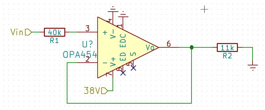
When applying a power supply of V-=0V and V+=38.4V and using the part as unity-gain follower, the part  doesn´t operate for input voltages below 9V. But according to the datasheet, the part should operate for V- > 2.5V. Is this its normal behavior? Could you please confirm?


Best Regards,

  • Hi Reymond,

    Indeed, a correctly functioning OPA454 should operate with an input voltage down to (V–) + 2.5, or in this case +2.5 V above ground. Can you send us the circuit so that we can review it for application correctness?

    Are all of the OPA454 devices they have tried in the circuit doing the same thing? Is this a new, or existing, application?

    Regards, Thomas

    Precision Amplifiers Applications Engineering

  • Hello Thomas,

    Please find below the schematics for our application. They have seen the same behavior on 5 different device

  • Hello Reymond,

    If that schematic drawing is correct, then it presents some serious connection problems for the OPA454. The V+ pin is pin 7, and it connected to ground; while V- pin 4 is connected to the positive +38.4 V supply. They would be reversed. Then, the output Vo from pin 6 is connected to pin 3, the non-inverting input. That would constitute positive feedback, not the required negative feedback. Negative feedback is achieved by feeding a portion of the output signal back to the non-inverting input.

    The E/D pin 8 is connected to ground which places the amplifier in disabled (shutdown) mode. The E/D common pin 1 is referenced to V- and has a range of V- to (V+) - 5 V so it should be connected to the correct level.

    If help is need setting up the OPA454 schematic for a buffer operation, I can help.

    Regards, Thomas

    Precision Amplifiers Applications Engineering

  • Hello Thomas,

    Sorry, customer just to come back to me with their good schematic.Please consider the one below:

    Thanks in advance for your help.

    Pol

  • Hello Pol,

    I do not see any problem with the OPA454 buffer circuit as connected; however, in a practical circuit it is recommended that a power supply bypass capacitor be connected from the V+ pin to ground. I would expect this circuit to function correctly provided the input level is maintained within the specified common-mode voltage range and the output swing range limits are observed.

    It shouldn't be necessary to apply a voltage to the E/D pin to enable the amplifier becuase it has an internal pull-up. However, just to make sure there isn't an issue with the function try adding a resistor divider from the +38 V supply to the E/D pin such that the voltage between +2.5 and +5 V is applied to the pin. If it still doesn't operate as expected, then there must be another issue with the circuit, or circuit board.

    The OPA454 product receives full electrical testing before it is stocked. It is unlikely defective devices were supplied to the customer. Make sure that the OPA454 devices were obtained from an authorized TI product distributor. If the customer continues to have problems they may want to order some new OPA454 samples via the TI product webpage and check them in their application circuit. If the circuit still doesn't work, then there is something else we are overlooking.

    Regards, Thomas

    Precision Amplifiers Applications Engineering