This thread has been locked.

If you have a related question, please click the "Ask a related question" button in the top right corner. The newly created question will be automatically linked to this question.

OPA377-Q1: Differential output oscillation

Part Number: OPA377-Q1
Other Parts Discussed in Thread: OPA377, OPA237

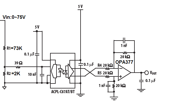
I have a question regarding to OPA377 and OPA237. I use your OPA377 in differential amplifier. The schematic shown below.

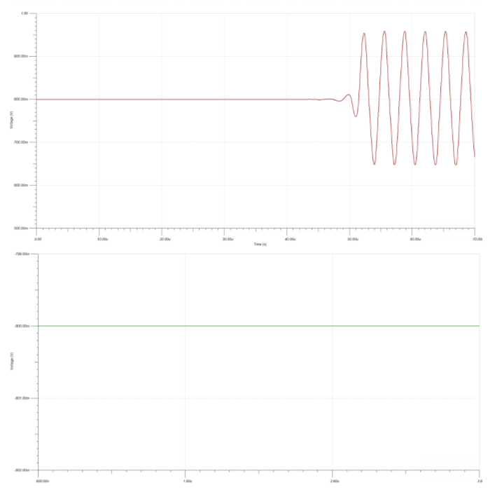
The voltage I'm sensing is 32V. Voltage into the opto is 32V*2/75= 0.85V. The output waveform shows below.

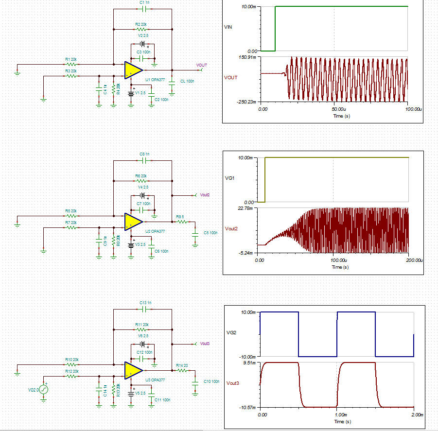
I did a simulation in Tina, with 1uV 50kHz disturbance, the output of differential amplifier is oscillating.

If I replace OPA377 with OPA237UA, the output is good even with 50mV disturbance.

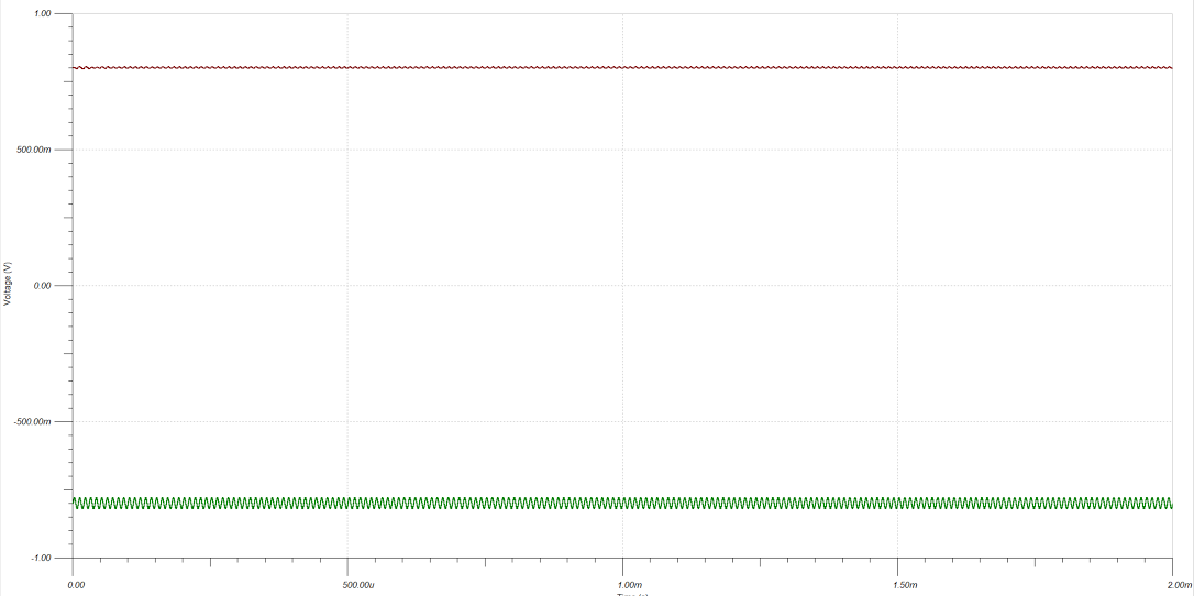
After replacing it with OPA237UA on my board , the output oscillation is gone.  May I know why these two OP AMP behave so different? And if I want an AEC-Q part to replace OPA237, what should I use?

  • Weijia,

    Very few op amps are capable of driving directly (with no isolation resistor) more than few hundred to few thousand pF load and OPA377 as well as OPA237 are NOT exception.  What you call stable in case of OPA237 is not quite correct - just that the magnitude of OPA237 oscillation is much smaller due to four times lower bandwidth and slew rate.  Btw, oscillation is NOT a function of the magnitude of the input signal and in fact inherently unstable circuit may break into sustained oscillation completely on its own being triggered by its own input noise or RF/EMI interference.


    In order to assure stability of any circuit configuration over process variations, a good rule of thumb is that the small signal overshoot should not exceed 25%, which is an equivalent of 45 degrees of phase margin - see curves above. However, the absolute maximum overshoot should never be allowed to be greater than 40% (30 degrees phase margin) so the output settles within reasonable timeframe.  If you look at the Small-Signal Overshoot vs Load Capacitance graphs below, you will notice that by the above standard you may drive with OPA377 only 300pF capacitive load while OPA237 can drive up to 1nF.  However, you are attempting to drive 0.1uF load (100,000pF) thus more than two orders of magnitude higher than the parts can handle.

    Therefore, in order to stabilize the circuits, you must either lower the output capacitor to the values discussed above or add  20 ohm or larger isolation resistor between the op amp output and its capactive load - see below. I have also attached the schematic so you may use it for your own simulations.
    Please also watch a video series discussing the cisuit stability unde following lonk: