A related question is a question created from another question. When the related question is created, it will be automatically linked to the original question.
If you have a related question, please click the "Ask a related question" button in the top right corner. The newly created question will be automatically linked to this question.
Part Number: PGA103 Other Parts Discussed in Thread: PGA204
HI,dear:
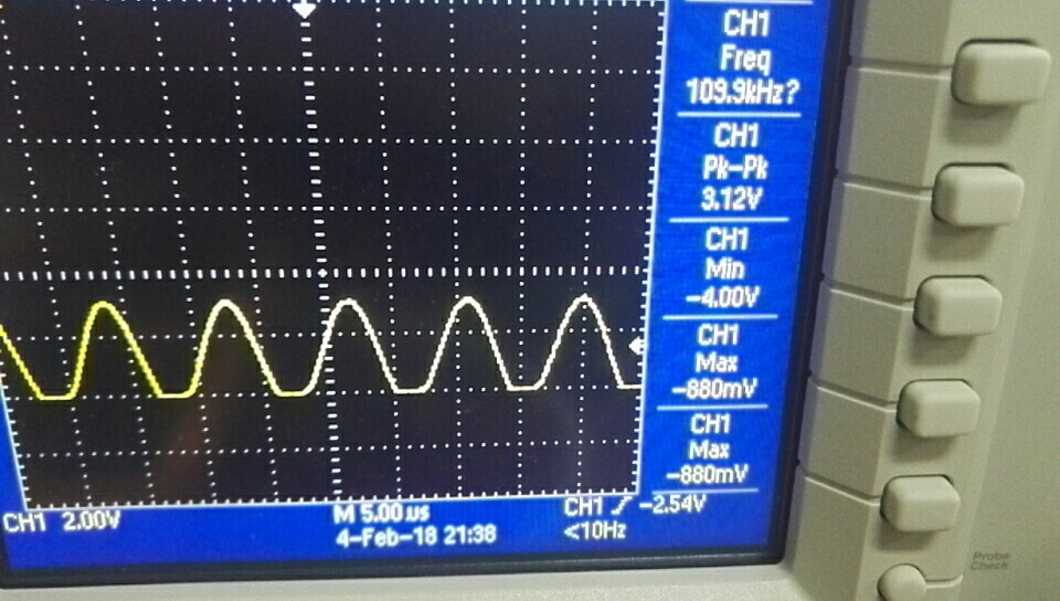
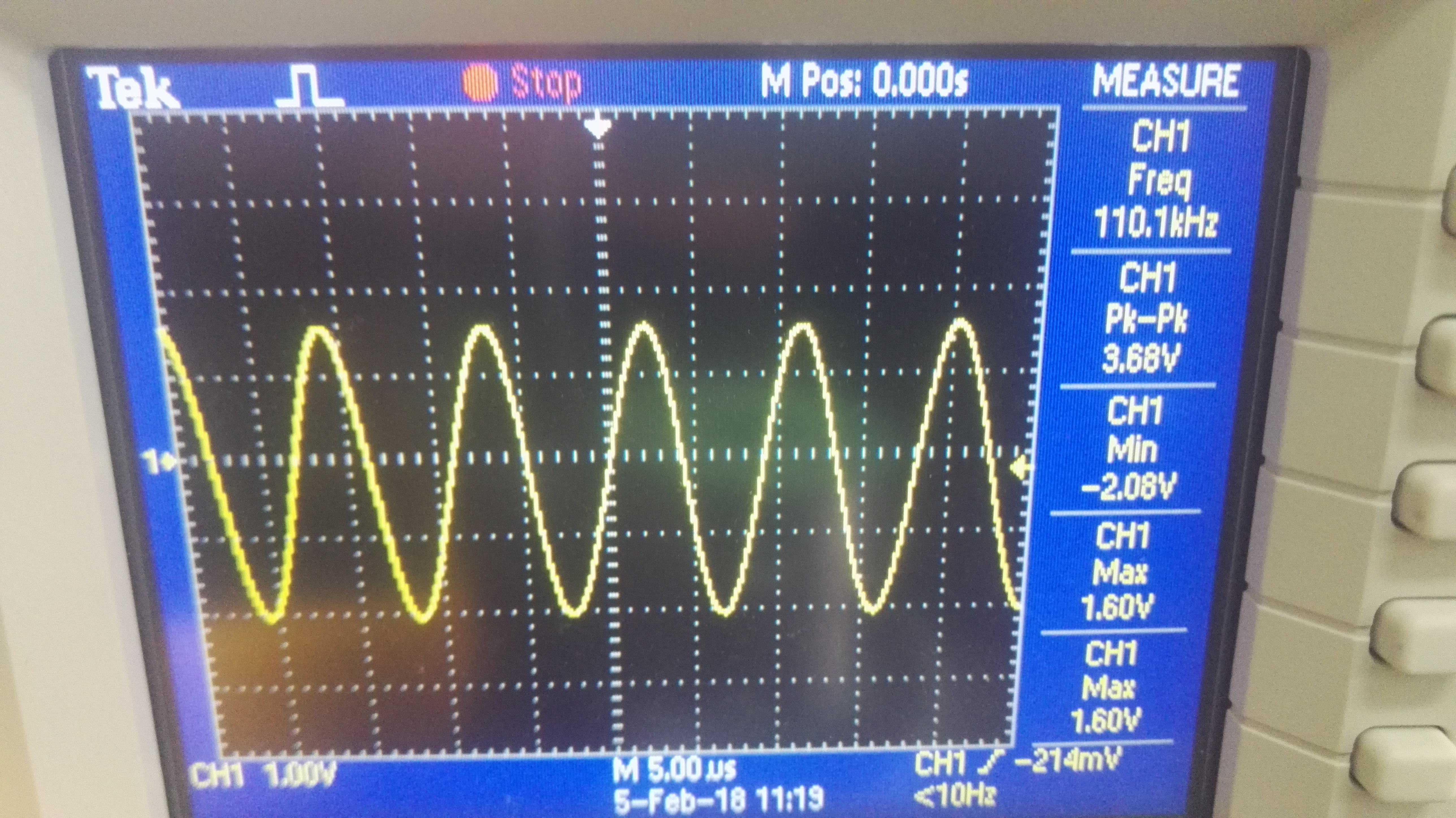
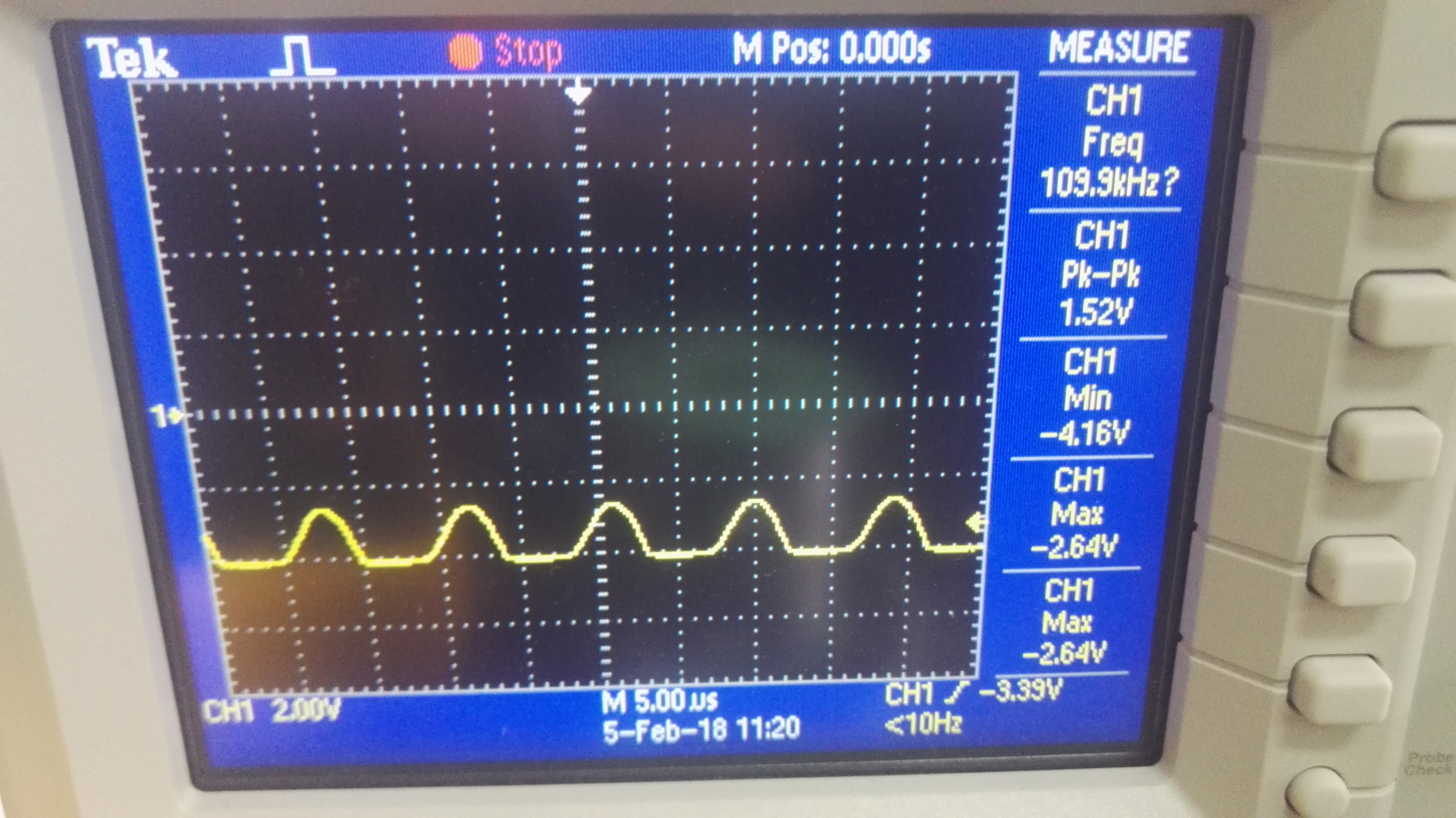
I made a circuit with PGA103, however, the signal is cut off as pictures. The input is sine and the amplitude is 40mv PK-PK, the power is ±5V. why the output is cut off?
Check to make sure that you do not have any dc offset voltage being applied along with your input ac signal. If dc is present it too would be amplified and the output will move toward one of the output swing rails. If it swings too far the output will clip.
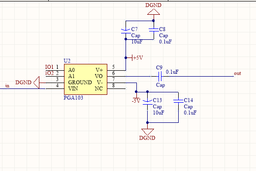
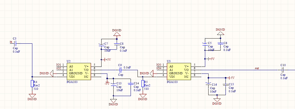
Please provide us your PGA103 circuit diagram, gain setting method, input signal source information, and output load information. We can look the information over and see if something was overlooked in your setup.
Regards, Thomas
Precision Amplifiers Applications Engineering
I suspect that you are running into output swing limitations due to the low +/-5 V supplies you are using with the PGA103. Even though the PGA103 can be operated with a supply as low as +/-4.5 V, its Electrical Specification table is written for operation with Vs = +/-15 V.
A parameter that becomes an issue at very low supply voltage levels is the Output Voltage specification. For positive output swing the limits are (V+) –3.5 min, and (V+) –2.5 V typ. For negative output swing the limits are (V–) +3.5 min, and (V–) +2.5 V typ. Therefore, with +/-5 V supplies the swing limit could be as low as +/-1.5 V.
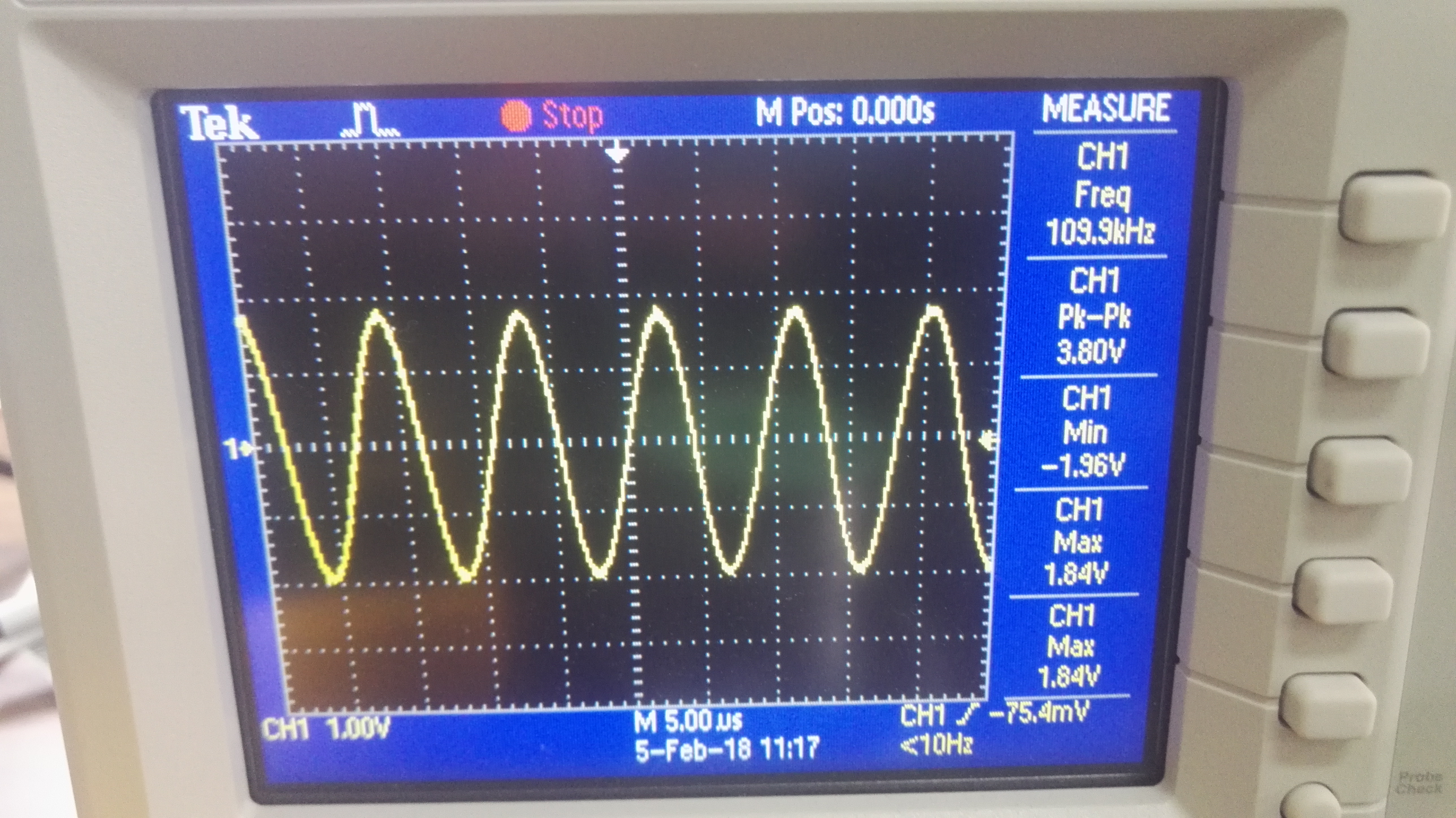
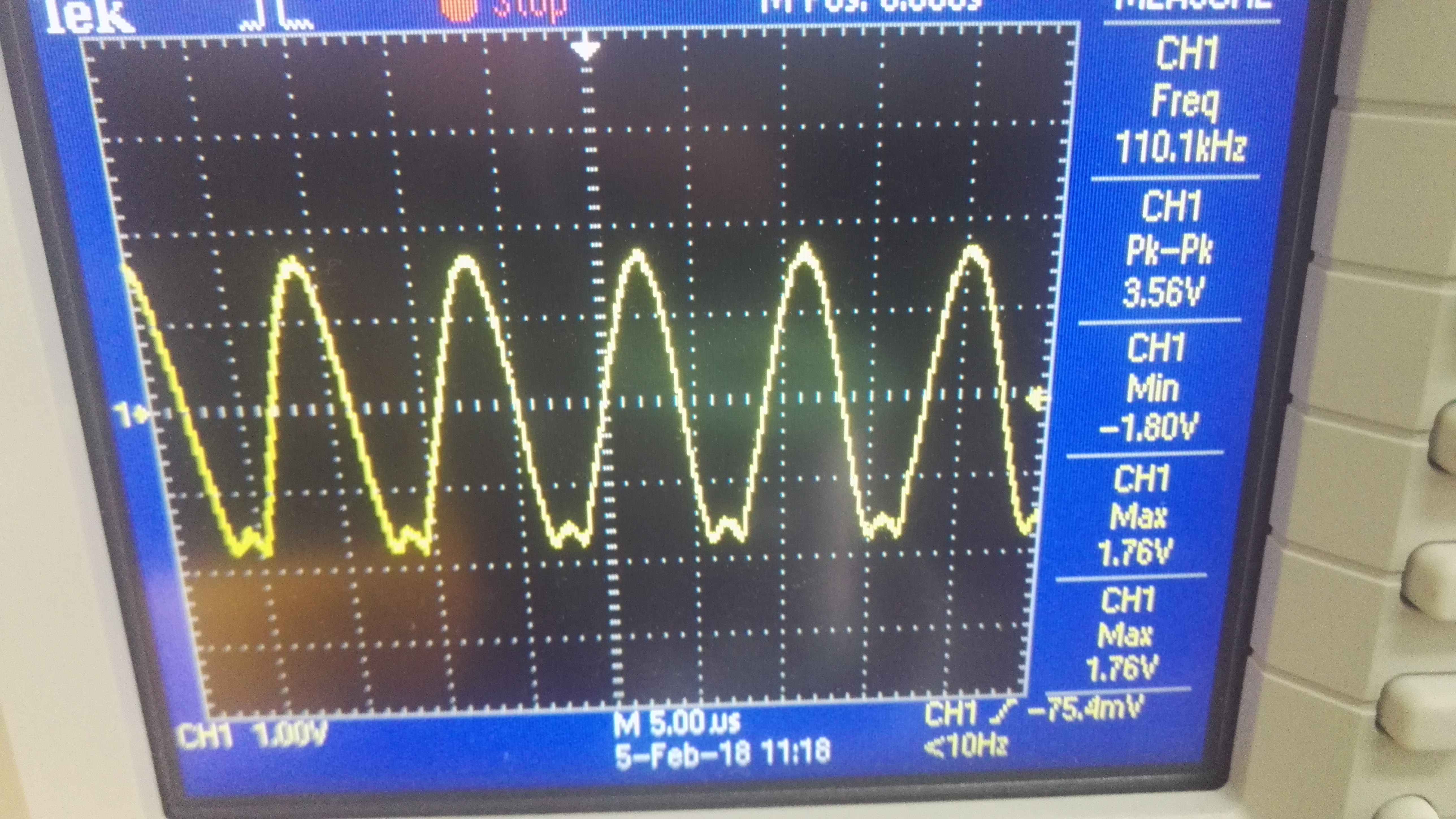
Your Figure 3 shows the G = 1 V/V output condition and it is evident that the output is beginning to clip on the negative peak. It appears that in Figure 5 there is enough dc offset introduced that the output is again being driven into the negative output swing limit. Again, once up against the swing limit the waveform will be clipped as seen.
Would it be possible for you to increase the +/-Vs levels in the circuit? If so, you can then see if the output behaves as expected. You may need to increase the supplies to obtain satisfactory operation.
Regards, Thomas
Precision Amplifiers Applications Engineering
Sorry,I can’t supply the circuit of PGA103 with ±15V,due to all other circuit are supplied with ±5V. Do you any other chips to recommend? Or, the others advised me that add a pull-down resistor in the input? In fact, I tried it and found it’s effective when the value of pull-down resistor is 510. However, it doesn't work when the value of pull-down resistor is 2.2k, can you explain the theory of this method to me?
The resistors R4 and R5 shown in your schematic provide the dc return for the PGA103 VIN input, input bias current. A dc voltage drop is developed across each resistor which is the product of the input bias current and resistance. The voltage drop will be larger for the 2.2 k resistor than it will be for the 510 ohm resistor, by a factor of about 4x. That voltage acts as an additonal offset voltage component which is amplified by the PGA103 gain setting. Likely, the offset with the 510 ohm resistor is small enough such that the output is not as close to the swing limit as it is with the 2.2 k resistor at R4 and R5.
The TI PGA amplifier products are optimized for +/-15 V supplies, and operation at +/-5 V will result in compromised electrical performances. One PGA that looks like it is capable of a wider output swing range when using +/-5 V supplies is the PGA204. Its output voltage is specified with IO=5mA, as (V+) –1.5 V minimum, and (V+) –1.3 V typical. That is much closer to the supply rail than the PGA103 can achieve. Even though the PGA204 output swing is specified with +/-10 V supplies the POSITIVE and NEGATIVE OUTPUT SWING vs TEMPERATURE graphs on PG. 8 of the datasheet indicate the output swing is close to +/-4 V with +/-4.5 V supplies. That should be more in line with what your application requires.