Because of the holidays, TI E2E™ design support forum responses will be delayed from Dec. 25 through Jan. 2. Thank you for your patience.

This thread has been locked.

If you have a related question, please click the "Ask a related question" button in the top right corner. The newly created question will be automatically linked to this question.

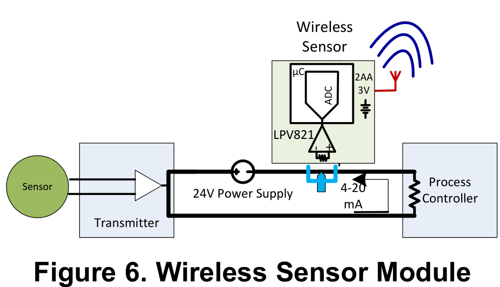
LPV821: lpv821, I want to useLPV821 as 4-20mA signel measure , as the picture below, snoa978a, wireless senser mode, How could i achieve the wireless measure, what is the way/device/senser could measure the 4-20mA ,many thanks ~

Part Number: LPV821

  • Andrew

    this is an interesting application.  I think this will work since the circuit you drew just floats on top of the line and monitors the current of the loop.  I will draw something up for you later today, tomorrow worst case, and post a circuit for you.

    Chuck

  • Chuck

    many thanks~ , my e-mail : Andrew.liu@wpi-group.com
  • Andrew

    What closed loop bandwidth do you require. The lpv821 has 8kHz of unity gain bandwidth.

    The more gain I use, the less closed loop bandwidth the circuit will have. But using higher gain allows me to use a smaller shunt resistor value and thus minimize loop voltage loss. For example, if I apply a gain of 100v/v, the closed loop bandwidth will be 80Hz. I don’t believe the current gets changed at a high frequency but wanted to get your input before making a recommendation.

    Chuck

    Sent from my iPhone

  • Andrew

    here is the basic concept of how you would accomplish.  the wireless sensing node you are creating essentially floats on the loop bus line.  In this example I am assuming it is a 24V PLC supply that is powering the sensor transmitter.  A non-inverting amplifier configuration would suffice for this application as I have shown in this diagram.  All you need to do is connect the battery ground on the sensor transmitter side of the shunt resistor that is being used to sense the loop current.  I chose a gain of 100v/v but that could be adjusted depending on bandwidth requirement and how much voltage drop you are willing to tolerate on the loop.  Hopefully you will be able to see my attached circuit.  If not, I will upload again.

    Chuck

    wireless loop sensing.pdf

  • Dear Chuck

    I get the  attached circuit, many thanks~