This thread has been locked.

If you have a related question, please click the "Ask a related question" button in the top right corner. The newly created question will be automatically linked to this question.

OPA2322: Output issue

Part Number: OPA2322
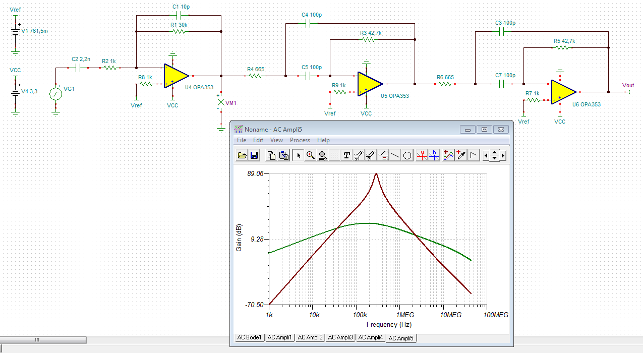
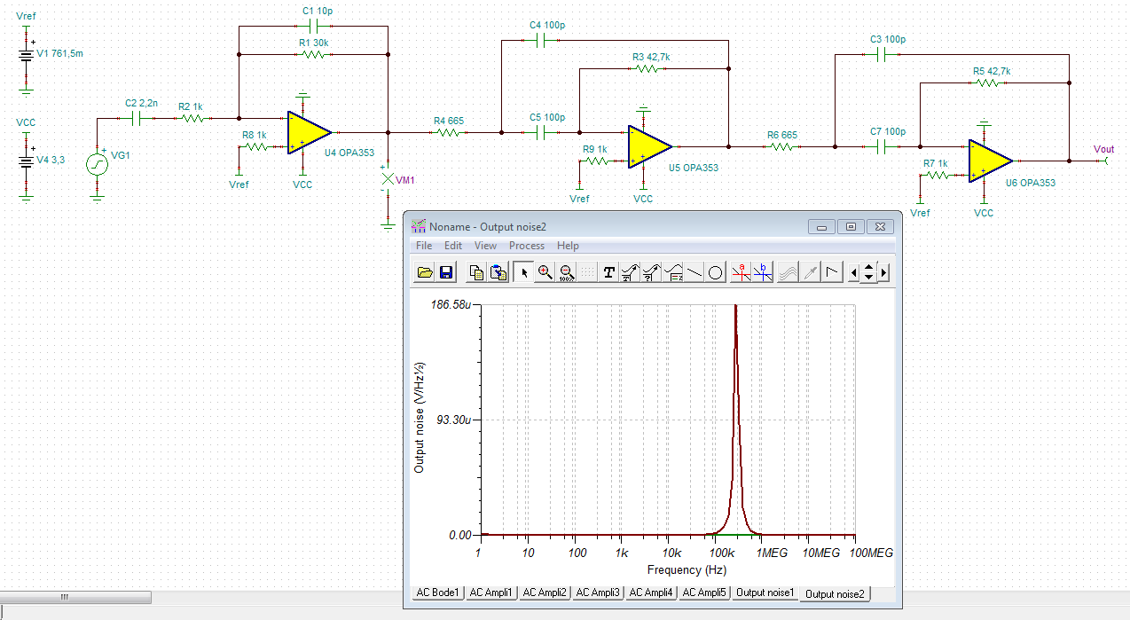
Other Parts Discussed in Thread: OPA353

Hello.

Our customer has been using OPA2322 for several years. However, We found problems in these months.

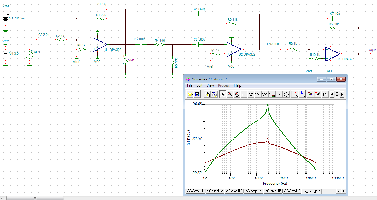
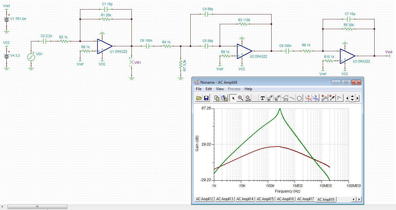
After confirming, We found that there are some differences in the output signals ripple between normal and defective products.

Can you please help to explain the abnormalities in this part? Please refer to the attached report. Thanks for kindly help~

Daifuku ultra-sonic 不良分析_0724y18.xlsx

  • Hi AJ,

    Thanks for the question and providing information. To really assist, I'm going to need a little more information.

    * Can you provide more of the schematic? It is going to be crucial for us to understand what type of circuit configuration the op-amp is in.

    From the information you've provided, I'm unclear on whether or not the input signal is just noise or if it's an actual signal that you're trying to amplify. * Can you provide any further information about the input signal (blue curves)?

    * Have you performed an A-B-A swap? Take the op-amp from the board which isn't working and switch it with the op-amp on the board that is working. Do the results stay the same?

    * In your provided testing, why is VCC changing?

    I did notice that you tied the shutdown pin of this device to ground in the schematic. If you're actually using the shutdown pin, please tie that pin to VCC and see if that changes the results at all.

    Thank you,
    Paul
  • Dear Paul.

    Good day. Thanks for you kindly reply.

    Please reference schematic and more clear information on attached file. Gain is 20 x 55 x 30 = 33000.

    We change the U3 problematic OPA2322. The issue is follow problematic OPA2322 to other board.

    The failure rate in these months exceeded 0.2%. But problematic OPA2322 are pass ATE test from TI.

    So we additionally verify that the voltage is changed to find the difference. It will be different on different voltages.

    We need to know if we have ignored what kind of the specifications then got such results.

    I mentioned the same problem on E2E before. It is just that this problem has not been solved. Please refer to the following.

    Thanks for you kindly help.~

    Daifuku ultra-sonic 不良分析_0725y18.xlsx

    DIAFUKU_PR_ULTRASONIC_RECEIVER_BOARD_20180725.pdf

  • Hi Aj,

    haven't we discussed the same issue here some time ago?

    e2e.ti.com/.../695447

    Have you tried what I have suggested there?

    Kai
  • Dear Kai.
    Good day.
    This is the same problem that we discussed before.
    We also try your suggestion before and just only one solution are worked.
    We cut off GND_B and GND_C then use a 0.01uF between GND_B and GND_C. The problematic OPA2322 are work. But good OPA2322 will fail.
    This case has been in mass production for a few years. However, this problem has only occurred in these months. We want to know which specification difference caused this phenomenon to occur.
  • Hi AJ,

    My first thoughts are that this issue is either noise or stability. Can you run the following tests and share the results?

    * Tie ULTRASONIC_RECEIVER_B to ground and measure the output RMS voltage and peak to peak voltage. This will help us understand what the overall noise of the system is. Compare the results of a good system and a bad system.

    * Send a small pulse into the input so that we can see the % overshoot.

    Some further questions:

    * In the schematic, what is the value of C29 and C27? Are they 0?

    * What is the desired supply voltage?

    * Can you describe the input signal (amplitude, frequency, etc)?

    * How did you get a gain of 55 for the second stage? By my calculation it's a gain of 110.

    My stability analysis seems to show that each stage of the filter is stable, I've included the overall TINA schematic here for you. The overall gain of the circuit is 66,000 according to my math and TINA. If you look at the attached schematic, you'll see the noise analysis and the potential for quite a lot of noise given the high gain of the system.

    Daifuku_OPA322_Ultrasound.TSC

    A general word about noise in op-amps. We give the noise value as a typical spec, it is not guaranteed. It is possible for the silicon process to shift a little producing different values of voltage noise from lot to lot and this may be what you are seeing.

    -Paul

  • Dear Paul.
    Good day.
    We will try your suggest then update for you soon.
    About your question please reference on below.

    * In the schematic, what is the value of C29 and C27? Are they 0?
    A : Yes. Is 0 Ohm.
    * What is the desired supply voltage?
    A : 3.3V
    * Can you describe the input signal (amplitude, frequency, etc)?
    A : Frequency is 300KHz and the amplitude is small. We will check it for you.

    Do you have any suggest that other products can be applied to such an application?

    Maybe we will change solution for next project. Thanks for kindly help~
  • Hi Aj,

    you should redesign the filter section. I mentioned earlier that a Q=6 for the bandpass is too high. You can see this from the following rule of thumb: A single OPAmp bandpass has a gain of 2 x Q^2 at the center frequency (R30 and R33 are in parallel!). To work properly the OPAmp needs to have an open loop gain which is ten times higher: 20 x Q^2. In your case this means an open loop gain of 57dB at 300kHz. But the OPA2322 has only 37dB. This is just the gain the bandpass must provide, according to 2 x Q^2= 2 x 36 = 72 = 37dB. So, the OPA2322 even does not have any gain reserve at all.

    But there's another mistake: Due to the high Q the input impedance of U3A presents a massive load to U3B. U3B even shows a ripple in the frequency response at 300kHz resulting from this. When the input impedance of bandpass is increased the ripple almost disappears:

    I also mentioned earlier that the phase margin is considerably eroded when running the bandpass at a Q of 6. So, I would split the Q of 6 into two separate bandpasses with a Q of 3 each.

    Is there any reason why you use the voltage divider R33? This only lowers your overall gain. If the gain is too high why not lowering R21 or R22?

    Kai

  • Kai's points are good - you may consider using a higher bandwidth device and see if the results improve. With more bandwidth, you'll have better performance at 300kHz.

    A device like the OPA353 or something from our high speed product family: www.ti.com/.../overview.html

    -Paul
  • Hi Paul,

    yes, it's a good idea to use a faster OPAmp. I have taken your OPA353 into the simulation and it looks good:

    Of course, instead of 665R and 42k7 resistors also 680R and 43k resistors can be used. I have chosen a Q of 4 to get enough overall gain.

    A phase stability analysis (not shown here) gives a noise margin of 19° at 100kHz for each bandpass. This should be enough.

    Noise analysis also shows good results:

    aj10.TSC

    Kai

  • Dear Paul and Kai.
    Thank you for your help. We will check it. Thanks~