Because of the Thanksgiving holiday in the U.S., TI E2E™ design support forum responses may be delayed from November 25 through December 2. Thank you for your patience.

This thread has been locked.

If you have a related question, please click the "Ask a related question" button in the top right corner. The newly created question will be automatically linked to this question.

THS3061: CMRR at 10 MHz

Part Number: THS3061
Other Parts Discussed in Thread: THS3062, , THS3001, LM6171, THS3491, OPA694, OPA2694, TINA-TI

The CMRR plot for this part seems odd, and we wonder if there is an error.


See www.ti.com/.../ths3062.pdf, Fig 31 on Page 11.

We are interested in the CMRR at 10 MHz, and do not understand how the CMRR for THS3061 and THS3062 can be so vastly different, given that these are exactly the same Op-amp, just that one is a single and one is a dual. Specifically :-

THS3061, CMRR = 20 dB at 10 MHz
THS3062, CMRR = 52 dB at 10 MHz

It is hard to believe that the dual op-amp version should have a CMRR 32 dB better than the single OP-amp version?? Is there a mistake here?

Also puzzled as to why the CMRR should should get BETTER at >100 MHz, but not of concern to us. In contrast other OP-amps like THS3001 look as expected, with CMRR getting steadily worse at increasing frequency..

Getting back to the primary question, can anyone confirm that CMRR at 10 MHz is only 20 dB for THS3061, but 52dB for THS3062? And if this is true, then why so different?

FYI, here is why the CMRR matters to us. We need to build a unity gain differential amplifier. Both inputs will see a slightly distorted 10 MHz signal, with slightly different phase and amplitude. We need to look with great accuracy at the difference between these two 10 MHz signals that have similar phase and amplitude, thus the need for a differential amplifier circuit. This turns out to put severe demands on the CMRR performance of the op-amp. This is easily seen if the two signals were identical, in which case any observed output from the differential amplifier, on account of imperfect CMRR, would be an error in what we are measuring. I naively first used a 100 MHz voltage-feedback LM6171, an old favorite of mine that has no trouble reproducing a 10 MHz waveform with relatively low distortion. However, in this differential amplifier application it was a complete failure, producing a noticeably distorted difference signal, when I know that the difference signal is actually a pure sine wave, as confirmed by differential measurement using 2 channels of an oscilloscope. The THS3061/3062 seem like a good choice, but only if I can resolve whether the CMRR at 10 MHz is 20 dB or 52 dB! If anyone can suggest a better op-amp for the application, then that is also of interest. Low distortion is also a requirement. 

Colin

  • Hi Colin and welcome to E2E,

    Unfortunately, I was unable to determine why these two curves are so different. One suggestion is that different supply bypassing is used for a dual chip. As for why its CMRR increases above 120MHz, that is outside the bandwidth of the amplifier and should be ignored. For your application, is it possible to use a differential output? If so, a fully differential amplifier such as the THS3491 will give you good CMRR.

    Best regards,

    Sean
  • Hi Sean,

    Thanks for looking into this. It does seem unlikely that power supply bypassing would explain the vastly different CMRR plots. Surely we could assume that the professional TI engineers that produced these plots know how to provide correct and effective bypassing on the test fixture.

    The question remains unresolved, in that we cannot be sure that there is not an error in the published plots, and we can find no credible explanation for why the plots look so different for the single and dual versions of the same op-amp.

    I have ordered some THS3061, and may measure the CMRR at 10 MHz myself as this does not appear to be a difficult measurement. The CMRR vs frequency plot for the THS3001 shows the test measurement circuit used for that plot. Was the same test circuit used for the THD3061 plot of CMRR vs frequency? I presume it was, but TI have been naughty and not told us. :)

    Cheers, Colin

  • Hi Sean, I forgot to thank you for pointing me to the THS3491, which is not a fully differential amplifier as far as I can see, but I don't need a differential output anyway. The CMRR is not given, but broadly speaking the performance of this op-amp is truly state-of-the-art. I may not use it for this application, but will file it in my head for future reference. Colin
  • Hi Sean,

    The more I look at this, the more I am inclined to think that one of these plots is wrong. As an example of what we should expect, take a look at the specs for the OPA694 and OPA2694, two op-amps that are also identical except that one is single and one is dual. And we find, as expected, that the CMRR plots for these two op-amps are identical, being 44 dB at 10 MHz.

    Given that all evidence points to one of the THS3061 / THS3062 CMRR plots being wrong, I think that TI needs to look into this. As a professional designer, I need to know the correct CMRR for these op-amps, and for the THS3061 in particular. Would it thus be possible for you to look into this further? 

    Thanks,

    Colin

  • Hi Colin,

    I have ordered some THS3061s and THS3062s and will work with characterization to revisit this specification, and I will get the datasheet revised if necessary. I apologize about the THS3491, it is single ended.

    Best regards,

    Sean
  • Hi Sean,

    Thanks so much for that, really appreciated. I look forward to see what you come up with, and will share anything I learn as well.

    Cheers, Colin

  • Hi Colin,

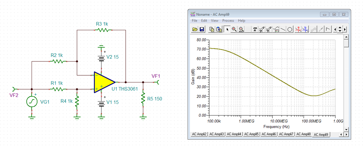
    you might be interested in the CMRR TINA-TI simulates?

    TINA-TI shows the same result for the THS3061 and THS3062. Both models are identical, very probably.

    colin.TSC

    Kai

  • Thanks for that Kai. The simulated result lies somewhere between the published THS3061 and THS3062 results. While the simulation provides a guide, simulation is never perfect and measurement is required to get an accurate CMRR plot, especially at higher frequencies.

    At this stage I have 2 issues. I think we would all like to resolve the apparent error in the published CMRR specs, and appreciate Sean's effort here. But with that said, I have come to realise that I have issues with my wideband unity gain differential amplifier regardless. My THS3061 arrived today, and I found it performed no better than my original lowly LM6171. My circuit is identical to yours above except that the resistors are 820R. It is well known that the resistors will need to be matched to a high degree of precision to obtain good CMRR from this circuit, but within limits that is easily achieved. But at higher frequencies, unmatched stray circuit capacitance will also unbalance the circuit and degrade CMRR. For example, at 10 MHz a stray capacitance of only 2 pF represents an impedance of about 8 kohms, which is only 10 times greater then the 820 ohm resistors that I am using, and significantly degrade the CMRR at 10 MHz. Right now I am sure this is the major factor degrading my CMRR performance. In retrospect, I would have laid out the PCB with particular care to minimise stray capacity on all connections associated with the + and - inputs. I can balance the stray capacities by adding a few pF here and there, and then see if I am eventually limited by the CMRR of the op amp itself. Due to unmatched stray capacitances, it is not as easy as you might think to build a differential amplifier with good CMRR up to 10 MHz and beyond. 

    Cheers, Colin   

  • Hi Colin,

    I apologize for the delay; I had to order an EVM. It appears that both parts' CMRRs follow the lower rating, currently designated on the datasheet as THS3061. The curve for THS3062 should be discarded. I will notify the higher-ups and begin a datasheet revision. Thank you for your patience and if you have other concerns I am here to help.

    Best regards,

    Sean
  • Hi Sean,

    Thanks for following this through. For my interest, what is an "EVM". The lower CMRR rating seems if anything a bit low, but TI is "safe" in quoting it. As I mentioned previously, the measured CMRR at 10 MHz and above will in practice depend on the stray capacitances and thus the PCB layout.

    FWIW, I did not achieve satisfactory results with the THS3061, but am getting excellent results from the THS3001, so am a happy little vegetable.

    Thanks again for your help,

    Colin