Hi Experts:
I am working on the single shunt current sensing solution like attached picture for my customer who is designing the motor drivers. In this usage of amplifier, the sensed waveform on the shunt resistor is the 2-level square waveform like below,
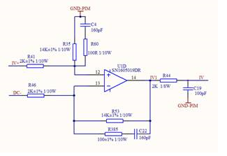
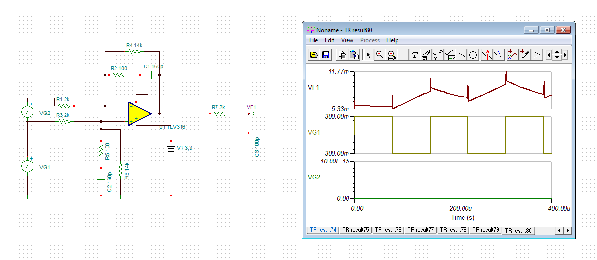
customer used the differential topology based on the TLV4316 , the schematic is below:
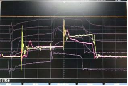
The issue is that there is the decline in the 2nd level, the sensed current waveform should be flat, please see the below capture waveform , the yellow one is the input signal (sensed current go through the shunt) ,
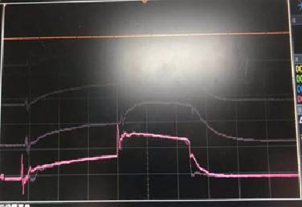
the purple one is the output of the TLV4316 is below:
If we removed the C22 and C4 ( integrating capacitor) , the decline will be worse than before.
The frequency of the waveform is 6.5Khz, the input amplitude of the input signal is from 20mV to 185mV, according to the gain (7v/v) , the range of the output signal should be 140mV to 1.3V , that means the output of the amplifier could jumping from 0V to range of 0.14V to 1.3V.
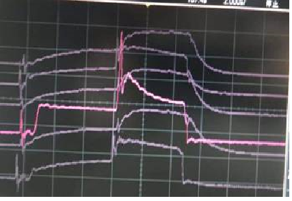
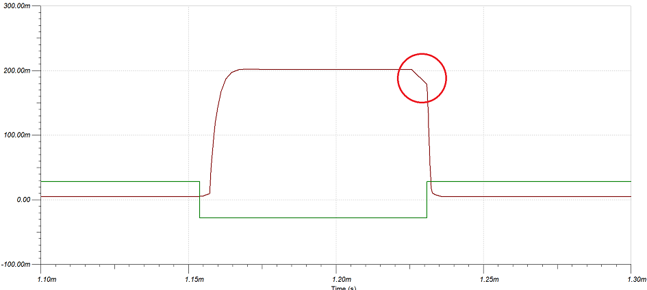
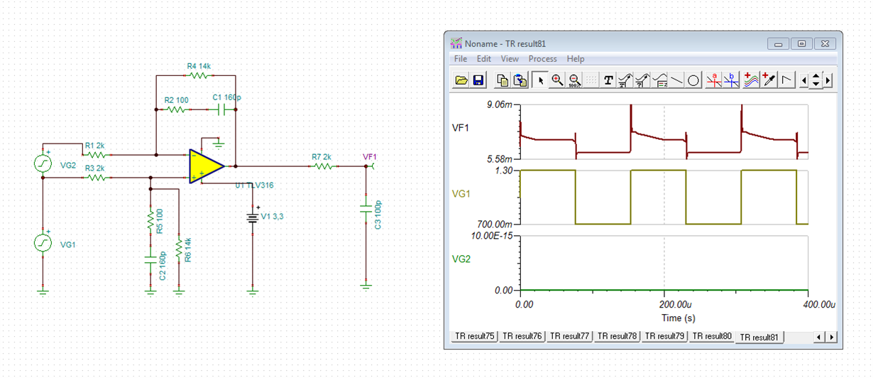
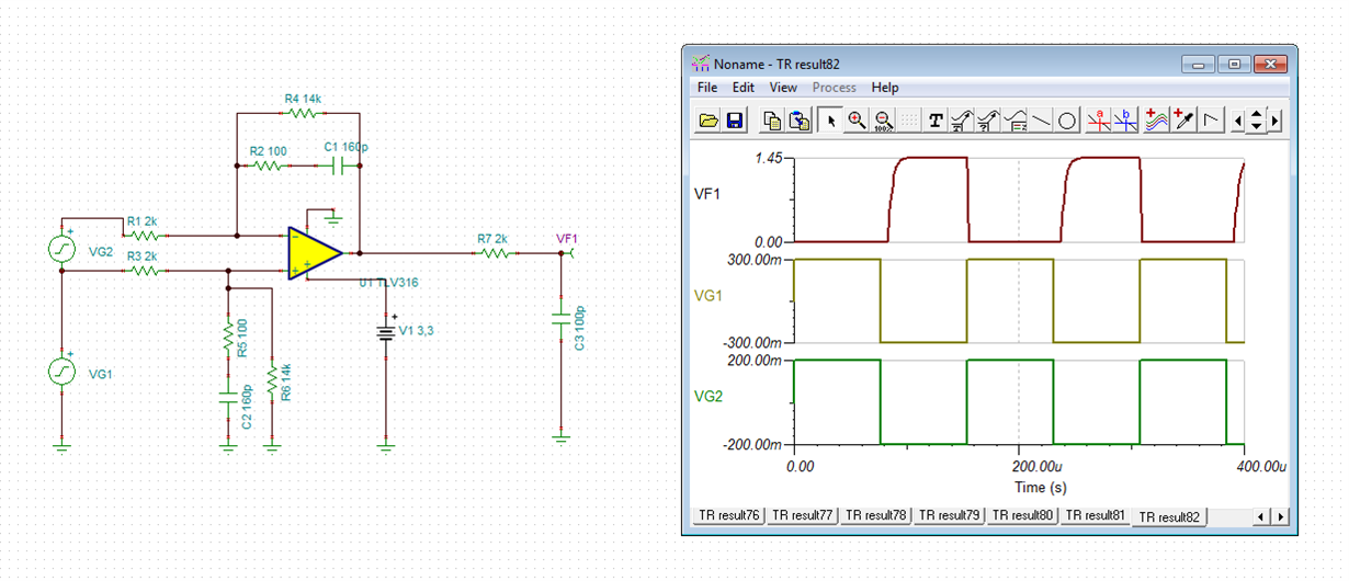
I don't know if it issue is caused by the poor slew rate in the small signal in the CMOS type of the amplifier, I did the simulation in TINA , and find the similar waveform like below, maybe the bipolar type of the amplifier is the better choice?


