Because of the Thanksgiving holiday in the U.S., TI E2E™ design support forum responses may be delayed from November 25 through December 2. Thank you for your patience.

This thread has been locked.

If you have a related question, please click the "Ask a related question" button in the top right corner. The newly created question will be automatically linked to this question.

THS4275: THS4275 Power Down

Part Number: THS4275
Other Parts Discussed in Thread: REF2920, INA826S

Hi,

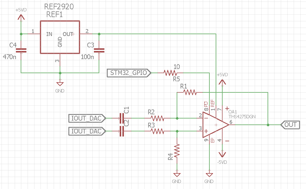
I'm using the THS4275 in combination with a REF2920. The REF 2920 has an output voltage of 2.048 V and is attached to the opamps REF pin. The opamp is operated in dual supply mode with +5V and -5V.

According to page 23 in the datasheet, the opamp should be enabled for a voltage larger then (2.048 V - 1V) = 1.048 V and disabled for a voltage below (2.048 V - 1.7 V) = 0.348 V.

I'm using a microcontroller output pin in push-pull mode with logic levels of 0 V and 1.8 V, unfortunately it is not possible to enable the opamp with the 1.8 V.

By using a !PD! - voltage of 5 V, the opamp is enabled.

Have I overlooked something in the datasheet?

BR

  • Hello Stenzer,

    The Power-down quiescent current in the datasheet has a typical value of 650uA. If the microcontroller is not able to provide this current the power-down operation will not run as expected.

    Best,
    Hasan Babiker
  • Hi Hasan,

    I'm using a STM32, accordding to the datasheet every GPIO pin is able to source/sink 25 mA. Further, I'm powering LEDs by the use of GPIO pins, so this should not be a problem.

    BR

  • Hello Stenzer,

    Do you mind providing your circuit configuration, along with the inputs to your device? You can email me at h-babiker@ti.com if you would not like to post this info onto the forum.

    Best,
    Hasan Babiker
  • Hi,

    attached you can find a simplified schematic.

    BR

  • Hello BR,

    My response earlier was incorrect and the 650uA is the quiescent current of the device during power-down mode. These results are not typical and the device should be enabled at a voltage level of 1.8V with a reference of 2V. You could possibly set the reference pin to GND, the enable and disable voltages will then be 1.8V and 1V respectively.

    Best,
    Hasan Babiker
  • Hi Hasan,

    yes, in my opinion the opamp should be enabled for a voltage of 1.8V.
    I have seen the enable/disable voltage levels for V_REF = GND. Unfortunately the enable-level with 1.8 V does not leave any margine, so this wouldn't be a reliable choice.

    Best Regards
  • Hey BR,

    Gonna order some THS4275 samples and test it out to see if we can replicate those results. Will get back to you then.

    Best,
    Hasan Babiker
  • Hey BR,

    In the meantime, do you mind confirming with a multimeter the voltage levels at the REF and PD pins (1.8V and 2.048V respectively)?

    Best,
    Hasan Babiker
  • Hi Stenzer,

    hmm, I would try to use a simple resistive voltage divider to generate the reference voltage.

    Kai
  • Hi,

    @ Kai: I already tried a voltage divider, but the devided voltage doesn't match the expected one. I don't now how the REF input is realized, it seems it has a resistive component.

    @ Hasan: The !PD! voltage is 1.8V and the REF voltage 2.168 V (0.1 V larger than it should be).

    I will try to attach an external power supply to the !PD! pin, and test the ON/OFF levels.

    Best Regards

  • Hi,

    I attached an external power supply to the !PD! pin. The amplifier is enabled for a voltage larger than ~3.65 V.

    In the datasheet the following statement is made:
    " Note that in order to maintain these threshold levels, the reference pin can be any voltage between (VS+/2) + 1 V to VS+."

    If V_REF has to be larger than (VS+/2) + 1 , than the values stated in Table 3 are wrong. which indicates the usage of voltages below (VS+/2) + 1.

    BR
  • Hi Stenzer,

    yes, you are right. A simple voltage divider might not do the trick, if the internal shutdown circuitry looks like figure 69 of datasheet of INA826S, for instance. There, a PNP is used to do the switching and the enable voltage and the reference voltage interact with each other. With the THS4275 a similar scheme could be used. So, it's a good decision to use a stiff voltage for the reference input.

    Kai

  • Hi,

    in the meanwhile I tested an other case. Therefore I connected the REF pin to GND. According to table 2 on page 22 the ON voltage should be >= 1.8V and the OFF voltage <= 1V. Resulting in a hysteresis of 0.8 V.

    I measured an ON voltage of ~1.45 V and an OFF voltage of ~ 1.35 V. This is far away from the values stated in table 2. Further, the hysteresis is far to small.

    Connecting the REF pin to GND and enabling the opamp with 1.8V works fine for my prototype, but for mass production that's not a predictable/reliable solution.

    By the way, I checked the package marking (see page 2) anf I'm definitely using the correct opamp (Marking: BFR).

    BR
    Stenzer
  • Hi Stenzer,

    the data in the table 2 only shows the guaranteed levels: TI guarantees that the THS4275 turns-on, if the enable voltage is >= 1.8V and that it turns-off, if the enable voltage is <= 1V. The actual levels are somewhere between, as you measured it with 1.45V and 1.35V.

    And you cannot conclude from the guaranteed values that there is a hysteresis of 0.8V. But if you switch the THS4275 by the help of a GIOP of microcontroller, hysteresis shouldn't be an issue anyway. The transition time of GIOP control signal should be much shorter than the time the THS4275 needs for turning-on and turning-off.

    Kai
  • Hi Kai,

    sorry, but I do not agree with your repley, especially by having a look on the shutdown circuitry of the INA826S. If the datasheet states an equation for the turn on/off voltage levels and the turn on voltage has to be ~3 times larger (~ 3.65 V instead of 1.048 V) somthing is wrong.

    Furthermore I would expect the previous mentioned hysteresis, at least within an acceptable range. How should someone design a reliable circuitry for industrial applications, if those values are more or less random. There is a huge difference between a hysteresis of 0.8 V and 0.1 V.

    @ Hasan: Have you tested the !PD! voltage levels so far?

    BR
    Stenzer
  • Hello Stenzer,

    Sorry for the delayed response, I will have an update for you within the next few days.

    Best,
    Hasan Babiker
  • Hello Stenzer,

    To begin Kai’s points are correct in which he mentions that the voltages between the enable and disable levels are not meant to represent a hysteresis of 0.8V. The actual thresholds are somewhere within that range of voltages, but by setting the PD pin to the enable voltage or above, the datasheet is giving the user a voltage level where they can be sure the device will turn-on. Based off this, I would recommend you ground the reference pin in order to use your design as intended. When connecting the REF pin to GND I was also able to generate a threshold of around 1.45V.

    We investigated the device and found that the information in table 3 of the applications section was erroneous and does not apply correctly to the THS4275. The correct function is that the threshold levels correspond with setting the REF pin to the positive supply when the pin is above mid-rail. Levels found in table 2 when the pin is below or at mid-rail are still correct. We will update the datasheet accordingly.

    Best,
    Hasan Babiker
  • Thank you for your time and your answer!