This thread has been locked.
If you have a related question, please click the "Ask a related question" button in the top right corner. The newly created question will be automatically linked to this question.
Dear Sirs, could you clarify the correctness of the different configurations for the SC-70 and SOT23 please.
Datasheet SBOS703F –APRIL 2014–REVISED OCTOBER 2016 page 4.
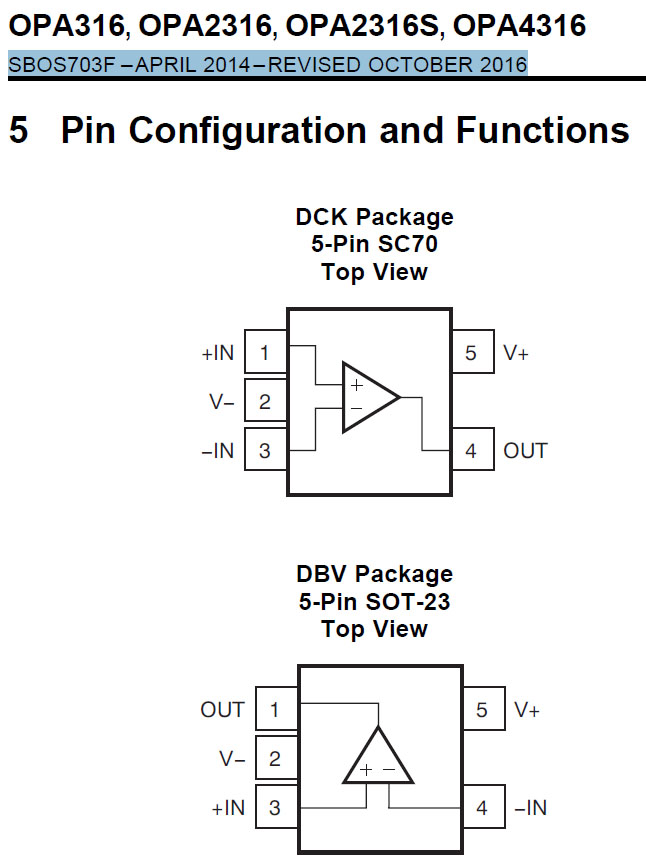
And last question if this picture is correct.
What are the reasons for these differences between SC and SOT configurations?
(except to facilitate the life of the designer)
For example: -in near -V in the SC case.
Best regards,
Vladimir.
Hello Vladimir,
As to your first question: this should be the correct pinout for these packages. I say this for two reasons. First, the datasheet has been released for almost five years now. So, it is highly unlikely that there would be a serious mistake like this. Second, this is a standard pinout for these packages. If you look at the datasheets for two of our newest parts, TLV9002 (page 6) or TLV9062 (page 6), you will see that the single channel packages have the same pin configurations.
Are you having some type of issue with parts that made you doubt the datasheet?
As to your second question, the answer is similar to the first. The packages are made this way primarily to comply with industry standards. This makes it easier for customers to drop in and replace parts pin-to-pin. You will see that there is one standard SC70 package and three standard SOT-23 packages: normal, "U," and "R."
Regards,
Daniel
Hello Daniel,
Thanks a lot, for detailed reply. Currently there are no questions or unclear points.
Good luck,
Vladimir.