


Other Parts Discussed in Thread: ISO7721, LMV762, LM311
Hai Paul Grohe,
Thanks for your clarification on the matter. Subjected to this query,please see the attached SiC Mosfet gate driver design of TI.
(Note: The actual web link cannot be copied here)
In the driver design,there is a feature called two-level turn-off given by TI.( See below the screen shot )

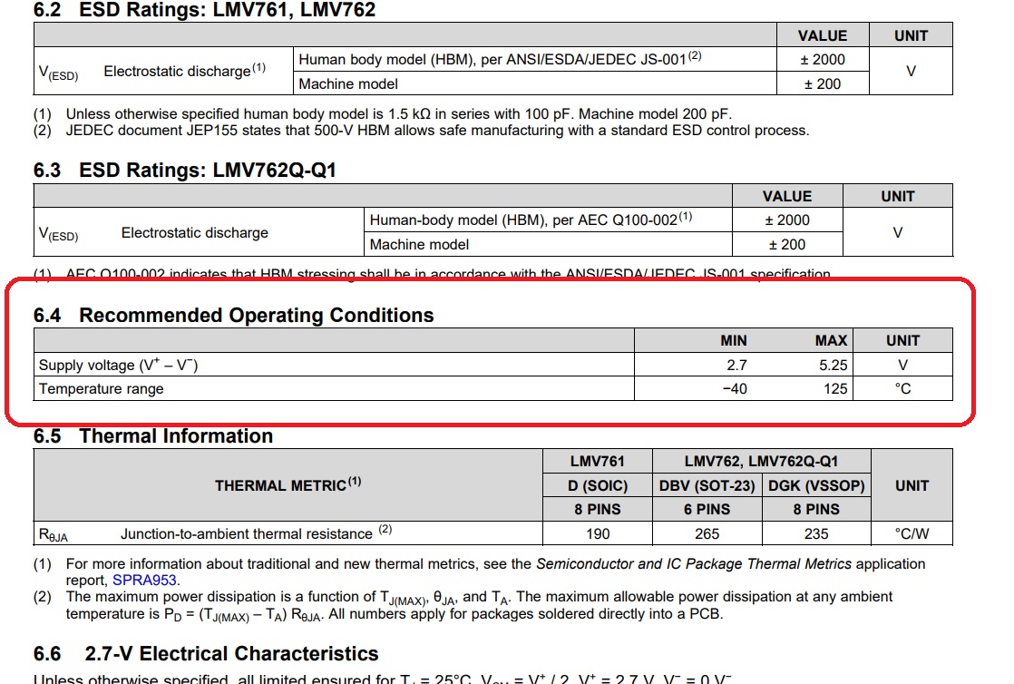
The screenshot of the two level turn-off circuitry is shown above where you can see U8A and U8B comparators LMV762 with +Vcc at +5V and -Vcc at -4V..So V+-V- is coming at 9V which is contradictory to the datasheet values
Also in the same design the comparator output is given to digital isolator ISO7721 . In case ,when the output of comparator clamps to -4V,the isolator does not have any provision to address this negative voltage .
The max Vin referred in the datasheet is limited to -0.5 to Vcc+0.5.
Please refer screenshot below.

Kindly look into the TI design refer to Fig.6 shown above.
Highlights:
Queries on
* Negative biasing voltage for LMV762-Q1
* Negative VIN voltage for ISO7720-Q1
Thanks....

