This thread has been locked.

If you have a related question, please click the "Ask a related question" button in the top right corner. The newly created question will be automatically linked to this question.

LMC662: High temperature opamp (> 200 Deg C) to replace LMC662

Part Number: LMC662
Other Parts Discussed in Thread: OPA211-HT, OPA820-HT, OPA2333-HT, THS4521-HT, LMC660, LMP7721, OPA2333, TINA-TI

Hi !!

Need Help to select  high temperature opamp having temperature rating  >200Deg C as replacement for LMC662

Requirement:

1 ) Need part with Input Resistance > 1T ohm

2) operating Temperature > 200Deg C

2) all other parameters equal or better than LMC662

Regards

  • Ron Michallick,

    plz  clarify the  following

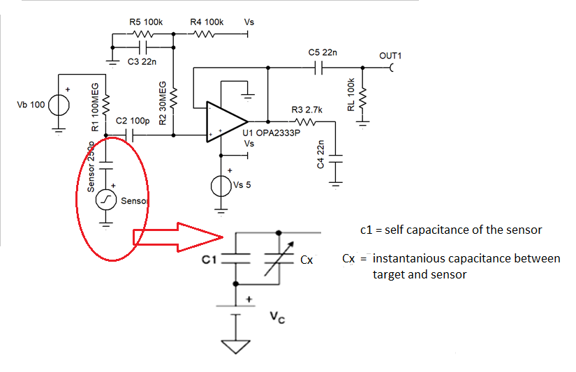
    1) you have shown signal source Cx in series with the fixed sensor capacitance C1 (250pF) in you circuit. please explain why?

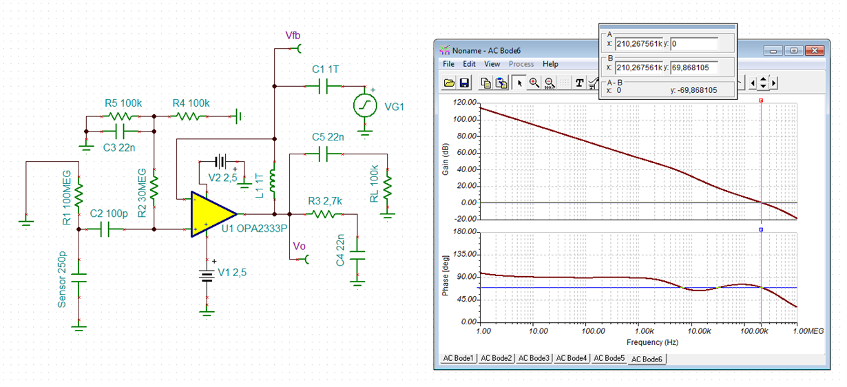
    2) to do the stability analysis should I consider the differential input  capacitance in parallel with common mode capacitance of non inverting terminal at the input of the opamp or will it be automatically factored by TINA-TI upon  selected the opa2333 model ?

    3) for stability analysis should I use the approach as shown in below example for  breaking the loop and taking measurement?

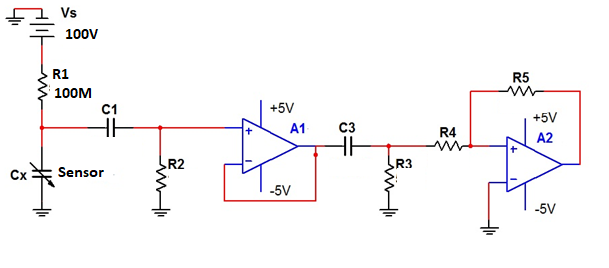
    4) Suppose I add an non inverting amplifier stage after the buffer(input stage).  The  Stability analysis for buffer and amplifier stages should be separately carried. out. is this approach correct ?

    Regards

    Kiran

  • Kiran,

    1) I just guessed at the sensor model; it is just roughly approximate
    2) Cd is so small compared to capacitance on non inverting input, so it doesn't matter.
    3) Yes, this is fine.
    4) Yes, separately. Each and every loop should be checked for stability. Inline circuits (not loop) don't need to be checked.
  • Hi Kiran,

    this could be your phase stability analysis:

    kiran3.TSC

    But don't forget to put your actual load (in parallel to RL) into the simulation!

    Kai

  • Hi Kai,

    Thanks for the advice!!

    1) The original ckt has single supply, you have used dual. Is there any specific reason?

    2) I have observed that single supply opamp is mostly operated by +5V  supply. Is there any disadvantage if I operate from a single -5V supply?

    3) I am planning to add a non inverting amplifier after this stage. Should I add the input resistance/capacitance  as load or there is no need to add load?

    4) While analyzing stability of the non inverting amplifier should I add C4,C5,R3 and RL at its non inverting input?

    Regards

    kiran

  • Ronald Michallick,

    thanks, your advices are very valuable.

    regards
  • Hi Kiran,

    I have given you the simulation file. So, check it out by yourself... :-)

    Kai

  • Ron Michallick

    Greetings

    I have couple doubts from the above scheme you have suggested (single supply OPA2333)

    1) upon switching on the 100V DC supply capacitor C2 charges to 100 V and later discharges. This will cause the opamp to see 100 V at the input. can I use zener diode (4.7V) to limit the voltage or is there any other effective solution.

    2) Is ESD protection required at the input of the opamp?

    3) If I want to add a non-inverting amplifier at the output of the opamp OPA2333 the DC reference (2.5 V) has to be added at the input of the non inverting amplifier again. This mean I have to use too many passive components. Is it better to use dual supply configuration or is there considerable advantage using  single supply configuration? 

    4)  want to keep the amplifier noise as low as possible,  so planning to choose resistors in the range of ohms (100, 200, 300 ohms). But this will result in increased current consumption. Is it OK to do so or should I select resistors in the range of few Kilo ohms?

  • Kiran,

    1) The maximum current of R1 is 1uA, how much voltage would 1uA create on R2? Diodes from input to both supply rails also works.
    2) Just don't touch it. If you must "touch it" then add ESD protection
    3) No big advantage or disadvantage to split supply. The op amp doesn't even know which which choice was made.
    4) Just keep thermal resistance noise -20dB or lower than the other noise sources will be good enough. Anything beyond that is a waste of supply current.
  • Ron Michallick,

    Greetings !!

    Thanks for the reply