Other Parts Discussed in Thread: TLV3501
Dear TI expert,
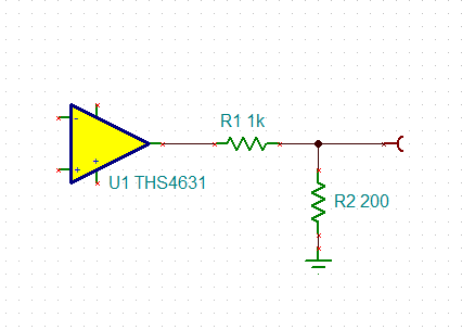
I use THS4631 to integrate a signal as fig1. And the actual PCB is as fig2. Due to power supplies, Vo will be saturated to about +18V. Since I want to compare the output with a reference by a high-speed comparator that is powered by +3.3V, I need to scale down the Vo to Vos, that is, 1/6 of Vo.
Currently, I use a regular slide rheostat as Rt1 in fig2, but Vos waveform is not good and deviates from theoretical waveforms obviously. In fig3, yellow is Vos, blue is Vo and Vo is intended to be halved . However, they don’t meet the proportional relationship.
Can you please tell me how to obtain a scaled down signal that follows Vo well and as precise as possible?
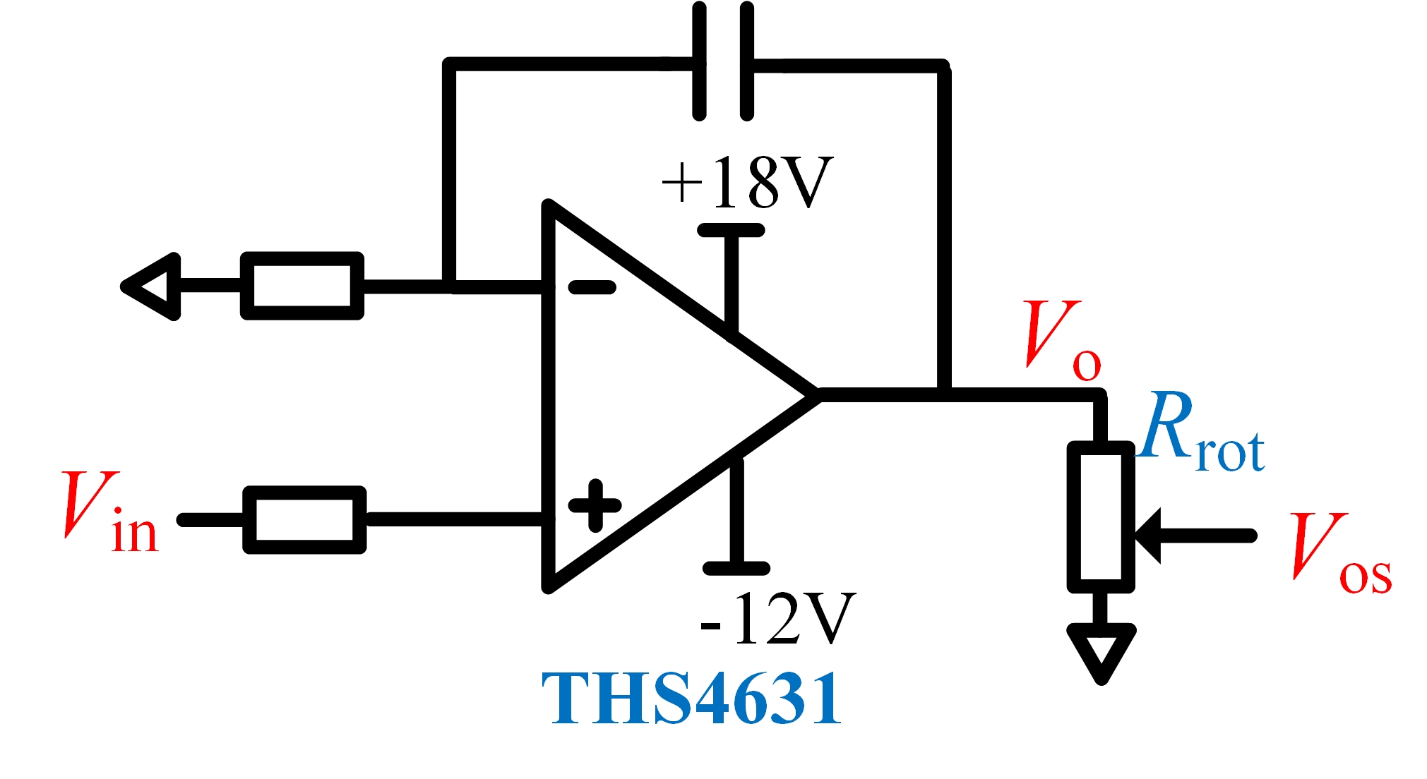
fig1
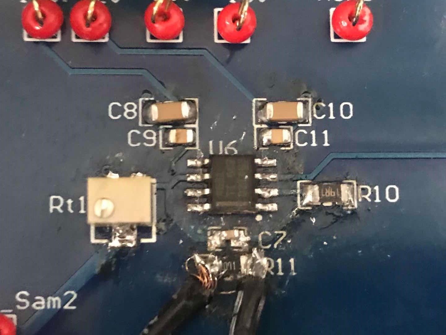
fig2
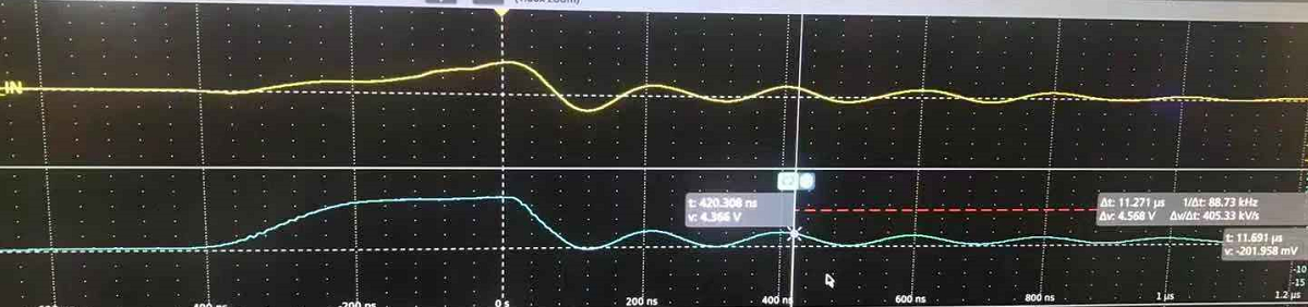
fig3
Best Regards
Yatao