This thread has been locked.

If you have a related question, please click the "Ask a related question" button in the top right corner. The newly created question will be automatically linked to this question.

INA128: Datasheet Spec for Settling Time, Input Range

Part Number: INA128

Hi,

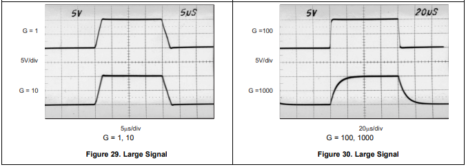
Does anyone know how the settling time for INA128/129 was measured or spec'd? When filling out the datasheet, what was the output swinging from to arrive at a 9 us setting time? I only ask because I plan on swinging the output from the positive rail to ~3 V, so I was hoping to understand what the settling time might look like for a transition like that.

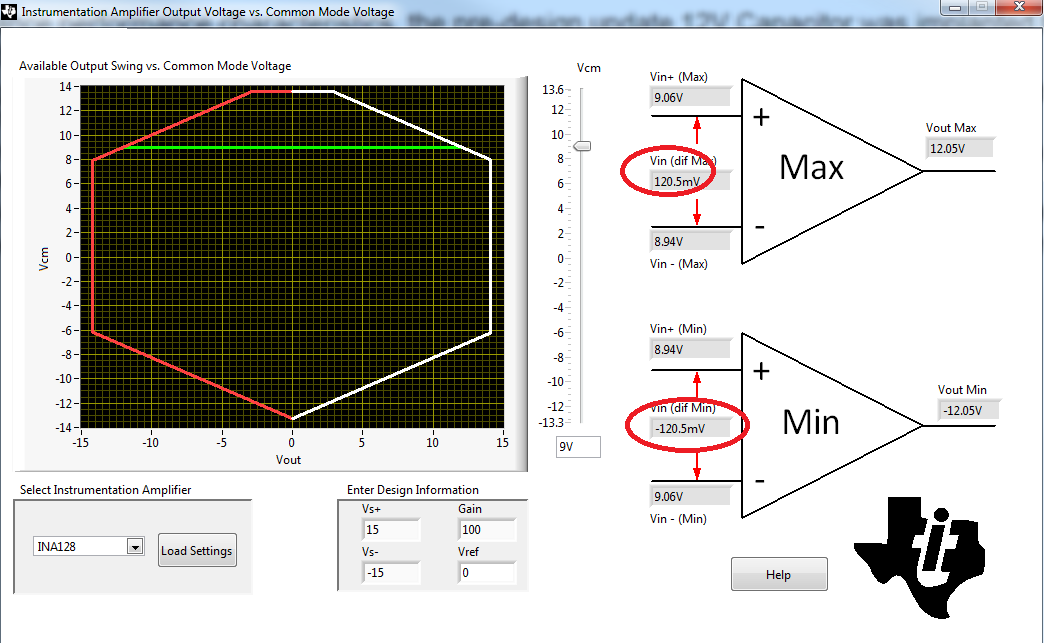
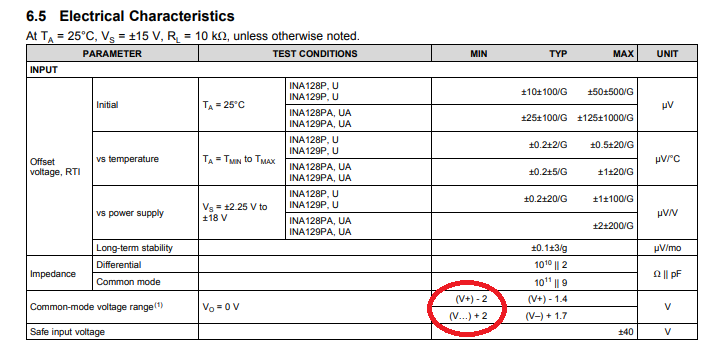
Also, a question about the input voltage ranges. The spec for input common mode voltage range (which I understand to be the average of the inverting and non-inverting inputs) has a max of 1.4 V lower than the positive rail, but the datasheet also says that the inputs are protected to +/- 40 V. My question then is what happens then if the input (V+ - V-) is at 40 V, which surpasses the spec for input common mode voltage? How will this affect the behavior of the amplifier?

Regards,

Michael 

  • Michael,

    The settling time of INA128 was measured with 10V output step voltage and appropriately scaled input signal for a given gain - see below.

    The typical INA128 input common-mode voltage range is from 1.7V above the negative rail up to 1.4V below positive rail BUT the minimum specified input range is only 2V away from each rail.  Also, as a differential input voltage causes the output voltage increase, the linear input range is limited by the output voltage swing of the front-end amplifiers A1 and A2. Thus, the linear common-mode input range is a function of output voltage of the complete amplifier, which depends on the gain, supply and reference voltage used (see performance curve in Fig 5 and Fig 6).  Therefore, in order to assure a linear operation of the instrumentation amplifier, you should download a free Vcm vs Vout calculator for instrumentation amplifiers under following link:


    The inputs are protected against the damage up to +/-40V BUT under such conditions the input voltage is way beyond the specified input common-mode voltage range and thus INA128 does NOT operate linearly; therefore, you may not expect a valid output to be present since under such case Vout is most likely to collapse on one of its rails.

  • Hi Marek,

    This is really helpful, thanks! I'm new to instrumentation amplifiers, so I want to relay my interpretation to you based on what I have understood.

    For a given Vcm, I have a certain range of Vout for which my output scales linearly based on my input (or Vdm, I suppose). At higher Vcm magnitudes, my amplifier essentially "saturates" earlier? My output voltage range decreases.

    In my application, I plan on dividing down a differential 1800 V by roughly 100, so this leads to me to 18 V at the input of INA128, so Vcm = 9 V. The calculator then tells me that the max output voltage is 12.05 (+/- 15 V supply, G = 100), so this means that my amplifier now saturates a little bit earlier. I don't actually care about this measurement, so the fact that I don't get a linear relationship here doesn't really matter to me.

    Please let me know if this all sounds right!

    Regards,

    Michael

  • Michael,

    Things just don't make any sense the way to describe.  How can you apply a differential input of 18V in gain of 100 (Vout=100*18V=1,800V) and expect the output to be within +/-15V supplies?  In the gain of 100, the maximum differential input you may apply is +/-120mV - see below.

    Also, do you actually apply the input signal of 0V and 18V?  If so, this is similarly not allowed.  None of the inputs may be above 13V on 15V supply;  Vin<(V+)-2V.

    If you need additional help, please show your schematic so we understand what is it exactly that you are trying to do.

  • Hi Marek,

    I can't provide my schematic at the moment, but I will edit my post when I can.

    Basically, I'm measuring a voltage across a switch. When on, I expect the voltage across the switch to be roughly 3-3.5 V. When off, the switch will have 1800 V across it.

    In my case, the only measurement that matters to me is the on-state voltage, which is 3 V. Therefore, I want to divide down the voltage across the switch to fit within the input spec of the amplifier and internally gain it back up by the same amount as the division to not lose any resolution when I eventually put this measurement through an ADC.

    My concern then is mainly with fitting my input within the input range of INA128. Since I don't care about the 1800 V measurement, I plan to divide this down to a safe level and have it saturate the amplifier when gained back up. My ~3 V will get divided down by 100 (30 mV) and internally gained back up by 100, so it will appear as roughly 3 V back at the output. At least that's the plan.

    Also, where does it specify in the datasheet that Vin must be less than (V+) - 2 V? I can only find the +/- 40 V spec.

    Regards,
    Michael
  • INA128 Absolute Maximum Rated input voltage is +/-40V but the linear input voltage range is specified in the common-mode input voltage - see below.