Hi everyone,
I am making some tests with LMH6552DEVAL but my outcome is not the expected one. My input is a LVDS signal which has an amplitude of 400mV. At the output, I am looking for a voltage between 0 and -0.5V for the positive cycle and the negative cycle being beyond -3.3V (that's why I have designed for Vcm=-3.5V, to centred the output signal around -1.7V). I have simulated on TINA my configuration:
I have designed for a gain of 16, having R3=R4=480 ohms and R1=R2=30 ohms. R5=R6=50 ohms are used to adapt the input differential LVDS signal. R10=R11=50 ohm are adapting the output oscilloscope probes (Rosc1 and Rosc2), creating a voltage divider at the output (that's why I have designed for 16 gain instead of 8). Everything looks marvellous in TINA:
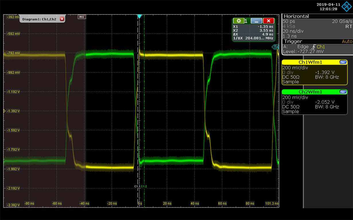
Unfortunately, when I go to the lab and making some tests I have found a non-expected behaviour. My output signals do not oscillate in the range we are looking for but, furthermore, something is wrong with the input V-. Taking a probe with another oscilloscope to measure the input V- I have realised that is being attenuated at the moment that is connected to the amplifier. The input signal V+ works perfectly but the output signal have the same amplification for both inputs, which does not make so much sense. The only difference between output signals is the offset as can be seen in the figure from the oscilloscope.
At this point I am wondering what can be wrong with the input channel V- and if this could be the reason of the bad behaviour in the output signal.
Thanks in advance,
Pablo.


