This thread has been locked.

If you have a related question, please click the "Ask a related question" button in the top right corner. The newly created question will be automatically linked to this question.

OPA859: Input common mode capacitance

Part Number: OPA859

Hi,

I am working on a differential probe with a the first opamp stages being OPA859's. The input common mode capacitance is said to be 0.62pF.

I could not find any reference regarding any change of that capacitance based on biasing or frequency etc.

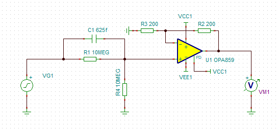
Please consider this schematic:

This forms a 0dB buffer stages with a flat response up to the point where BW starts falling (~730MHz @ -3dB)

Any change on the input common mode capacitance of the opamp would destroy the flatness of the frequency response that i see.

So, does the input common mode capacitance stay the same?

FYI: TSC file

OPA859 test.TSC

Regards

Manos Tsachalidis

  • Hey Manos, 

    Normally, you would not want to depend on parasitic terms but perhaps add small external C's to dominate the parasitic so its variation will not hurt too much,

    https://www.planetanalog.com/author.asp?section_id=3404&doc_id=565150&page_number=1

    I did test the model and it shows 0.63pF input Ccm using this approach. An article posting 6/7/2019 steps through these input C extraction issues. 

  • Hi Michael,

    Thanks for your message. I did that simple test with the opamp setup as a VF with a 10K which resulted in a 25.58MHz -3dB frequency.

    That corresponds to a 0.622pF. However, my concern is whether this capacitance in real-world applications gets affected by other conditions.

    One thing that i did not understand was the 10uF value used in the link that you included in your last post. Where does that come from?

    What did you mean when you suggested that i should add an external cap so that it would dominate the parasitic value of 0.62pF?

    Adding an external cap in parallel with the one formed between +IN and GND (in a split supply) is fairly understandable but what value are we talking about here?

    In order for that ext cap to dominate, a 100x or 1000x times the value of 0.62pF would be needed in order for variations in the Ccm to be negligible.

    That amount of capacitance would force me to use the same amount on the input (the one in parallel with the 10ΜΩ). Am i getting this right?

    Regards

    Manos Tsachalidis

  • Here is an example monte Carlo -

    I targeted nominal 5pF values and put 2% tolerance on the 5pF and 4.3pF extrinsic caps

    Then, I removed the internal 0.63pF with an external -0.63pF with no tolerance

    Then, I added that 0.63pF back in externally but with +/-30% tolerance 

    Get about +/-1dB gain spread and not much flatness spread -

    This is just and example showing methodology, not necessarily your desired design point - increasing the external C's with better tolerance will reduce this spread.