This thread has been locked.

If you have a related question, please click the "Ask a related question" button in the top right corner. The newly created question will be automatically linked to this question.

THS6214: THS6214 Power Consumption

Part Number: THS6214

Hi Team:

When I using THS6214 in broad PLC application. And now  some problem bother me .

In my design,Vs+=12V,Vs-=0V. And I have connected Iadj and Gnd with a 2k series resistor. Full bias.The differential signal input with 2Vpp.

1. When using, Is+ Quiescent current is nearly 350mA, so the chip is very hot.

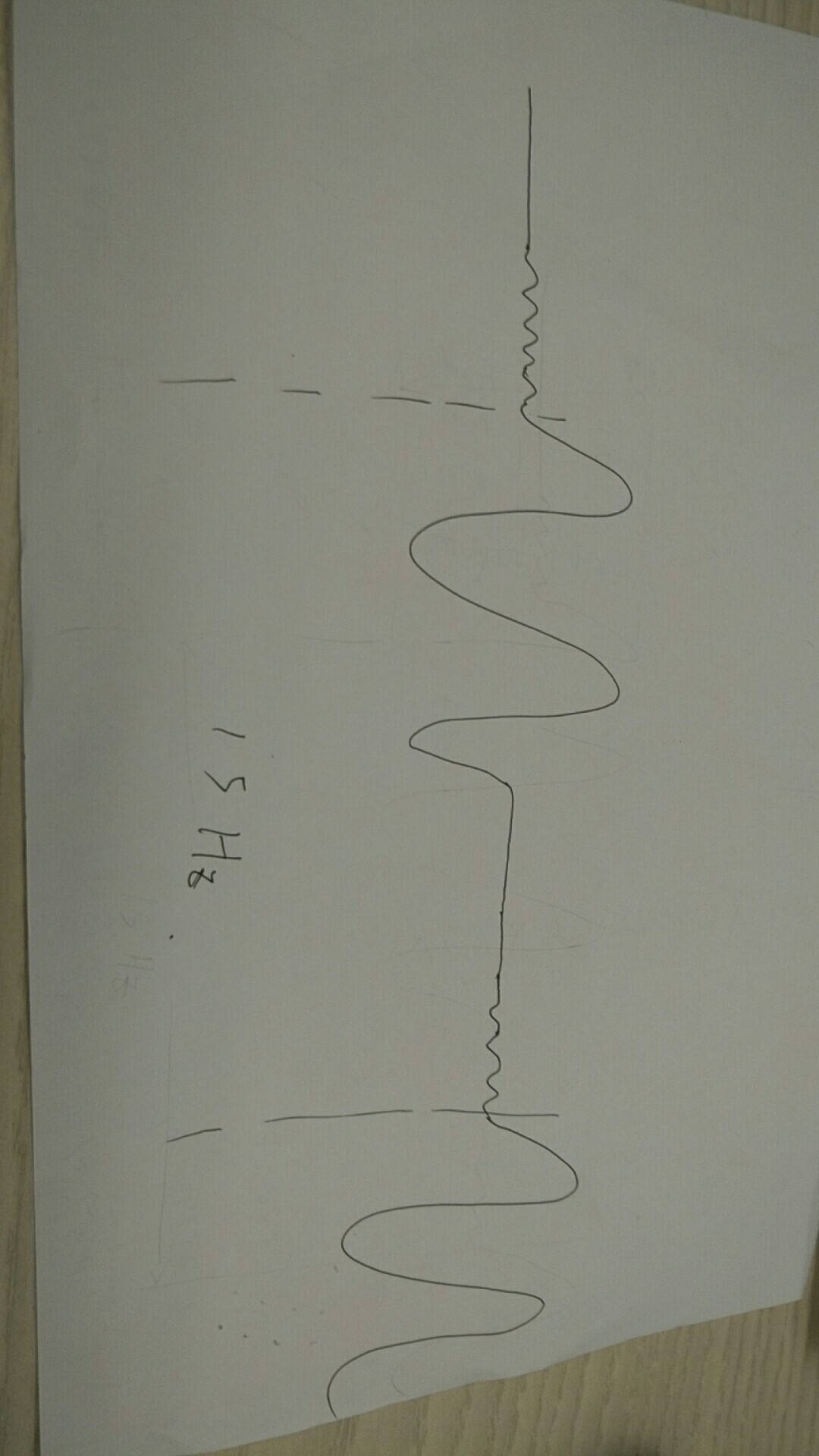
2. When using, the output signal is discontinuous,but the input is continuous.

Thanks

My design is shown bllow:

  • Hi,

    Can you describe further what the output signal looks like? Does it appear to be oscillating? 

    I've noticed on your schematic that you have put the two amplifier's in parallel. Are you able to look at this signal just using one amplifier port? Also, is there a reason you added resistors R100 and R114? Those resistors are usually included in the line driving application circuit. 

    Regards, 

  • Thanks,

    1.  my chip is damaged。 so  I can show the signal wave by my hands only.The input signal is 3MHz Sin wave.

    In my views,The output discontinuity is due to chip overcurrent protection or overheat protection.

    2.  The R100 and R114 has been shown in datasheet Figure82 where I marked it.