Because of the Thanksgiving holiday in the U.S., TI E2E™ design support forum responses may be delayed from November 25 through December 2. Thank you for your patience.

This thread has been locked.

If you have a related question, please click the "Ask a related question" button in the top right corner. The newly created question will be automatically linked to this question.

THS4503: High DC Current

Part Number: THS4503

Hi,

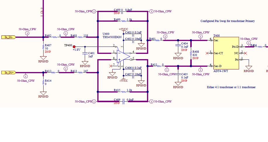
I used THS4503 in my board to convert a differential signal to a single ended one. I have used the same configuration as used in THS4503EVM, however, when no signal is connected the current consumption of THS4503 is almost 10 times more than what I expect (40 mA for each supply). When I connect the signal to the inputs of THS4503 this DC current decreases? I appreciate if you could help me to find the reason for these observations.

Regards,

Samaneh

  • Hello Samaneh

    First of all, normally you would use this FDA to convert a single ended input to differential output. 

    Also, attach schematics or TINA files - when no signal connected, the output might be railing differentially - depending on load, could create a lot of current. 

  • Hi Michael,

    Thank you for your reply. I have attached the schematic here. I appreciate your help.

  • Impressive detail, and everything looks really well done, 

    However, if you float In+IA- which it think you are saying you are doing, a large output DC offset will occur due to feedback divider imbalance, I don't see any blocking caps into your transformer, so any DC offset is going to create a lot of DC current. Try populating R401 and R411 with blocking caps. Large enough to pass your signal band. 

  • Oh and actually also, you cannot drive into a balun without matching resistors - so decide your turns ratio and load, and you need to drive into with the right resistor values. 

  • So I was looking at your output balun, that is one of many that I have a model for - here a sim of just balun running 50ohm matched across it - you show it stepping down 2:1. So with the matching loss this simple sim is midband -12dB gain. The -1dB span here is 3.9M to 383MHz - pretty good. 

    This little sim circuit attached - so you need matching resistors into it that as a 4:1 step down will make the balun out look like a 50ohm source. You need blocking caps to limit DC current - the balun is a dead short at DC so any output offset voltage will create a lot of current. I had to add those 10Mohm for the sim to find a DC operating point - the FDA will bias the input side of the caps , you might consider a 1Mohm to ground on the Balun centertap to DC bias that on the output side of the blocking caps.

    Balun simulation.TSC

  • Hi Michael,

    Thank you very much for your help. It solved my prblem.

    Regards

    Samaneh