Because of the holidays, TI E2E™ design support forum responses will be delayed from Dec. 25 through Jan. 2. Thank you for your patience.

This thread has been locked.

If you have a related question, please click the "Ask a related question" button in the top right corner. The newly created question will be automatically linked to this question.

INA206: Alert output switches between logic HIGH and LOW

Part Number: INA206

I am using INA206 at high side for overcurrent threshold monitoring. The load is supposed to draw 4 - 4.5 A current. I have set the overcurrent threshold at 4.7A using the Comparator 2. Now I am facing two issues while testing this circuit on a custom board:

  1. The CMP2 OUT goes low when around 3.4A or more is drawn by the load.
  2. After keeping the circuit and load active for 2.5 hrs I probed to find that CMP2 OUT was HIGH even 4.9A were drawn by the load. Even after resetting the power to the load whenever the threshold condition arrived the CMP2 OUT switched from HIGH to LOW a couple of times and then stayed HIGH.

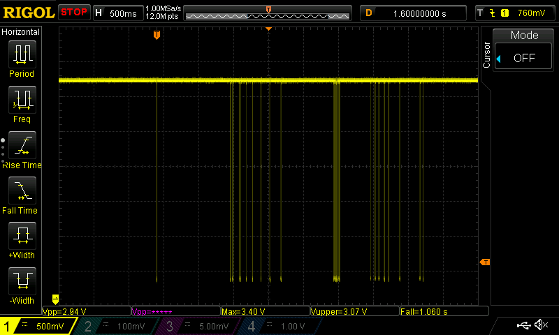
Attached are the screen capture of the scope probing CMP2 OUT, when load drew more than 3.4A current, and the schematic. Any idea why it is behaving so?

CMP2 OUT when load drew current beyond 3.4A

INA206_Power_monitoring_5A.TSC

  • Hi,

    If you have a customer design, I would inspect the PCB and make sure key components are soldered properly, including the divider. If you have a bread board setup, make sure all contacts are secure. Then probe COMP2 IN- pin to see if it is indeed above the 0.6V threshold with 3.4A load.

    Regards, Guang

  • Yes I have a custom design and I have tested the assembly. Regarding the switching CMP2 OUT, it worked fine initially. After the stress test I tested it again next day and it was working fine. I will try to reproduce that scenario again to do a thorough probing but till then if someone knows any known issue with this sensor please let me know.

    The COMP2 IN- was indeed above 0.6V (0.6327V to be exact) when 3.4A were drawn, but how come it was above 0.6V since in simulation it was 0.4347V at this point. Is there supposed to be this much error? Thanks

    Regards

    Sarmad

  • Hi Sarmad,

    There is a difference of ~200mV between 0.6V and 0.437V. This in turn corresponds to a ~400mV INA206 output difference.

    There could be a number of possible reasons why this is happening. Besides making sure the setup is OK, you might want to look into the test condition to see if it is indeed identical to the simulation. Further please check out section 8.4 of the datasheet where modes of operation are discussed. As you probably noticed, the amplifier is less accurate in certain regions than others.

    In addition to the comparator input voltage, you should also measure OUT and Vin, and be able to figure out where the error came from, the INA or the divider?

    Regards, Guang

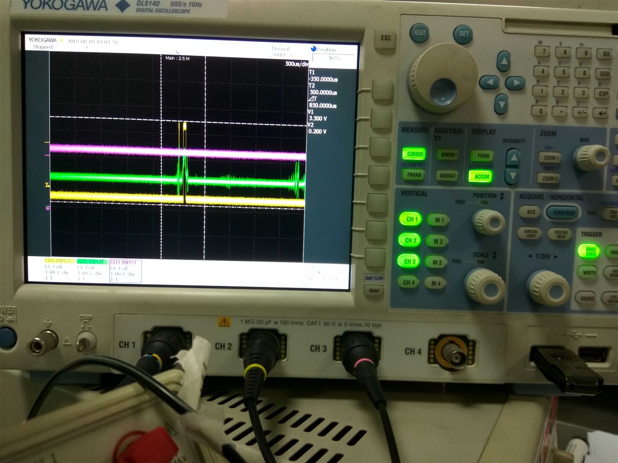
  • Another iteration of testing. While I was observing the CMP2 OUT (Ch1, yellow), Vref(1.2V) (Ch2, green), and Vout (Ch3, pink), a glitch occurred in Vref(1.2V) and the CMP2 OUT switched from LOW to HIGH and back, while Vout remained constant. Any guess for this glitch? Will probe further while observing the 3.3V Vcc  to INA206 on the scope as well.

  • Hi Sarmad,

    Do you use Vref for anything else or is this pin left floating? It appears something is coupling into this pin.

    Regards, Guang

  • No, I am not using Vref and its left floating. Though in last test iteration I soldered a wrapping wire to this pin for probing.

    Regards

    Sarmad

  • Hi Sarmad,

    You might want to make the wire short and away from other switching signals, if you want to keep probing on this pin.  

    Regards, Guang

  • Hi Sarmad,

    Please let us know if you have any updates. If your original question has been resolved, please click the “this resolved my issue” button to confirm. Thank you.

    Regards, Guang