


Other Parts Discussed in Thread: TLC2274
We use TLV9064 to repace TLC 2274 for current sensing. For the same circiut, the same board, the same measure way and tools, the noises of measured waves are obviously different. The details are shown as follow:
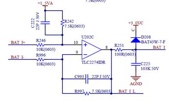
This is the circuit diagram:
When the amplifier is TLC2274, the test result as below
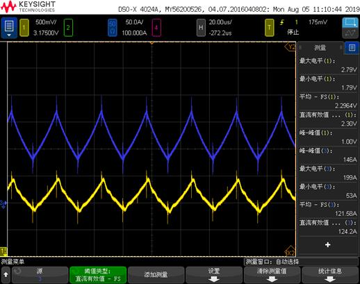
The blue curve is the real current wave, and the yellow wave is the measured output of the circuit.
When the amplifier is TLV9064, the test result shows as below:
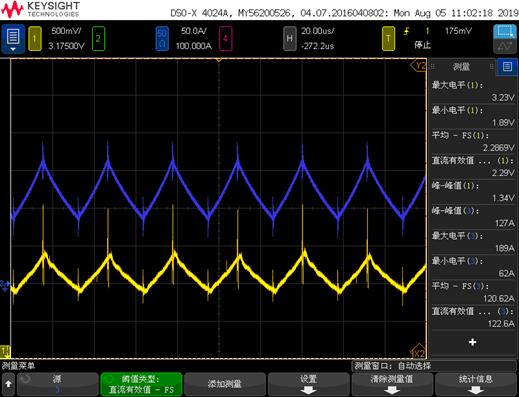
The blue curve is the real current wave, and the yellow wave is the measured output of the circuit.
The ration of blue curve is 10A/div in real.
My question is, where the nosie comes from? And why the measured waves of TLV9064 & TLC2274 diffrent obviously? What cause the diffrence? Is the different of specifications? If is the specifications cause the difference, I want know which specification causes
