This thread has been locked.

If you have a related question, please click the "Ask a related question" button in the top right corner. The newly created question will be automatically linked to this question.

LMP7721: AN-1798 Application Note - Noise Problem

Part Number: LMP7721
Other Parts Discussed in Thread: LM7705, LMC6442

Hi, 

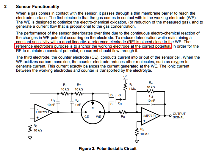
I've been building a potentiostat for my electrochemical sensor (in water) based on AN-1798 and below is the schematic of my circuit.

The circuit is petty much the same as the one in the application note, except that mine is biasing RE with VIN and the resistor and capacitor in transimpedance circuit are set to measure a smaller signal.

I'm perturbing the sensor with random pulses.  I've also attached the measured RE (left) and measured VWE overlaid with RE(right, Red:RE, Blue:VWE).

The problem I have is that the potential of RE, which is supposed to be just a pulse, is disturbed with these spikes, only at the downward edge. And the graph on the right shows that the RE potential is not an artifact from the measurement since it actually affects the VWE. This is happening only when the circuit is connected to the sensor so I assume it could be the stability of the feed back loop, BUT not clear how this can happen in one direction and as a spike. 

What I have tried so far is

1) Remove C11 and change the value of C12 to 100 nF as it is recommanded in alphasensor application note but it actually affects the stability and make RE very noisy.

2) RE was originally measured with ADC that has high input biased current so tried putting a buffer with low input biased current, but has no effect.

3) Disconnected R8 so that the guarding is not working, but also didn't work.

Any idea or suggestion to solve this problem?

Best,

GeehoonAAN_105-03.pdf

  • Geehoon,

    In your circuit you seem to allow RE node to float, which as should be expected results in its signal to show as a low-pass filtered (R1||C12) of the input signal.  The actual AN-1798 Application Note requires RE to be biased at correct potential thru Electro-Chemical Sensor or the circuit will have no feedback to control the output - see below.

  • Hi Marek,

    Thank you for the response. 

    I don't quite understand why the RE should be floating... When WE,RE, and CE are dipped into a solution for the measurement, a typical electrochemical model assumes that there is a certain impedance between CE and RE, and RE and WE. 

    Could you explain a bit more why you think the RE is floating?

    Best,

    Geehoon

  • Geehoon,

    It was not clear to me if you actually installed the electrochemical sensor for your measurement.  Hardly any op amp can drive directly 100nF and LMP7721 is no exception. Removing C1 while increasing C2 to 100nF creates the long time constant (delay) at RE electrode and that is the reason why potential on RE is not a pulse. In a single supply application with load connected to ground, the op amp is only able to source current while the sinking is limited to the quiescent current of the op amp’s output stage – this is the reason why you see RE disturbed only by negative transients. Using dual supply or driving a negative supply with LM7705 (negative charge pump) would enable your op amp to sink current down to -200mV and thus eliminate the disturbance of RE with negative spikes.

  • Hi Marek,

    I understand. Do you happened to know any dual supply, low input biased current op amp in your mind that can replace lmp7721?

    Geehoon

  • Hi Geehoon,

    The LMP7721 is our lowest input bias current amplifier. Depending on if you need the bandwidth, the next lowest input bias current amp is the LMC6442. To see a list of TI's low-voltage, low input bias current amps (less than 1pA maximum) please follow this link: http://www.ti.com/amplifier-circuit/op-amps/products.html#p1261min=0.9;3&p3247max=0.02;1

    -Tamara