Other Parts Discussed in Thread: OPA656, OPA2837
Hello everyone
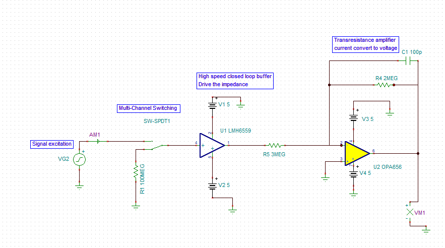
I use LMH6559 to assure that the excitation signals have low impedance.But refer to LMH6559 datasheet ,I still can't determine the circuit structure. I hope you can give me some suggestions. Thank you.
The following is my confusion and the current design of the circuit.
Fig 1. The current design of circuit
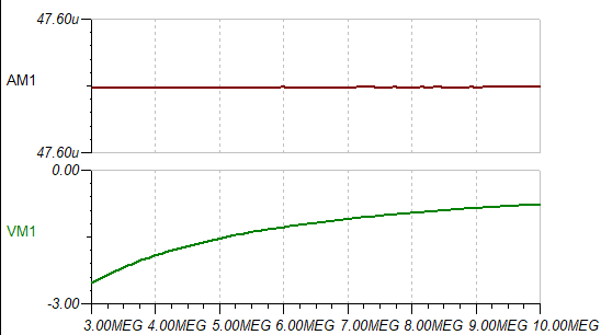
Resister value of R5
Fig2 DC simulation results
confusion: (1) LMH6559 is a close loop buffer so it does not require any external components ? So, can I use the above circuit structure ?
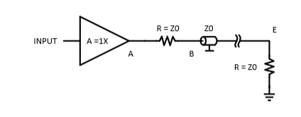
Fig3 Use one buffer to drive one transmission line
(2)Why is the voltage simulation negative? How can I turn the voltage into a positive value?
(3)If the above circuit structure is wrong,then how should I design it with the above component .(LMH6559 OPA656)
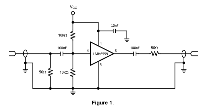
And refer to the datasheet,how do I choose the value of R and C (input and output).


