This thread has been locked.

If you have a related question, please click the "Ask a related question" button in the top right corner. The newly created question will be automatically linked to this question.

CCS/INA226: INA226 how to read 03h, 04h, 05h address

Part Number: INA226

Tool/software: Code Composer Studio

Dear,

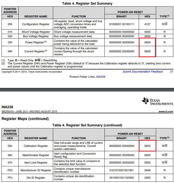
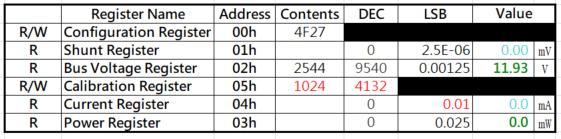
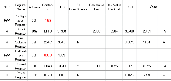
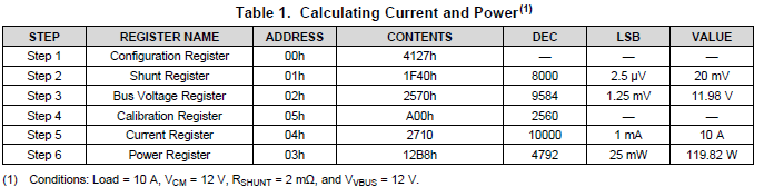
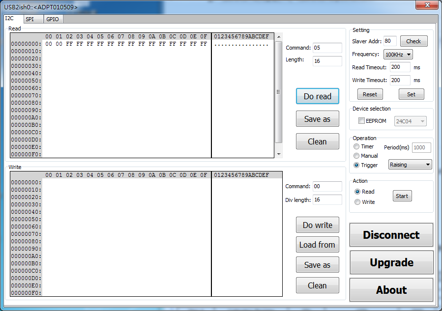
our client use INA226, and we can read 00h,01h and 02h, but we cannot to read 03h, 04h and 05h, GUI show "00"

how to read address 03h, 04h and 05h? 

schematic:

INA226 Schematic.pdf

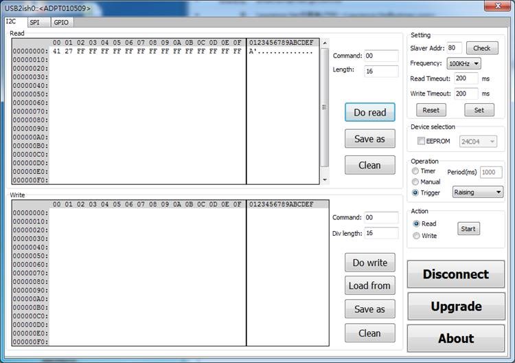
USB to I2C  Dongle   ( 00h )

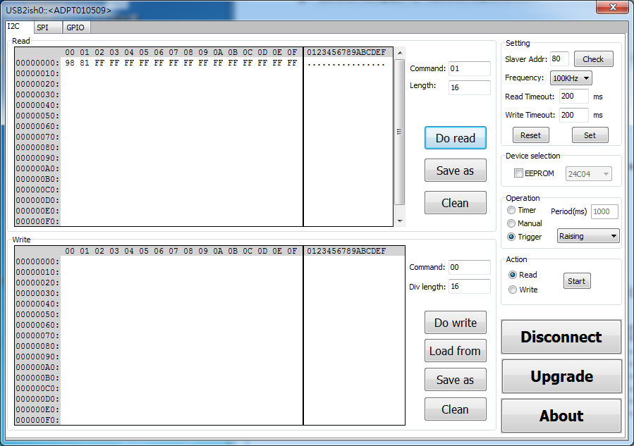
USB to I2C  Dongle   ( 01h )

USB to I2C  Dongle   ( 05h )

it`s code issue?

If any suggestion, Please advise me.

Thanks,

Best regards,

Lawrence.

  • Hi Lawrence,

    I notice you only mentioned READ operation; did your client try any WRITE command? The reason I ask is that by default, the calibration register (05h) has a value of zero. Therefore the current and power registers (04h & 03h) will also read zero. As shown in the register map:

    In order for the current and power registers to store correct values, the cal register must be programmed. Please follow datasheet section 7.5 for instructions.

    Regards, Guang

  • Hi Guang,

    The attached file is the INA226's test report that I have already test and recorded it.

    If some mistakes in this report,  Please let me know.

    Thanks a lot for your help !

    RSHUNT= 0.51 ohm

    VBUS=12V

    VS=5V

    Device Power Consumption = 45mA ~ 50mA

    PS. Is the Calibration Register's Value ( 12FF ) correct ?

    INA226.xls

  • Hi Lawrence,

    The results are not quite right. The reason is mostly due to the selection of current LSB and Cal register values. These two are related though equation (1), they are not independent.

    Also by inspection, a 44mA current over 0.51Ohm should yield 22mV, not 140mV. This reading is not affected by the selection of Cal value, please double check.

    If the current will always be less than 100mA, you could program the Cal register to 1024h, and set current LSB to 10uA as show in below table.

    Regards, Guang

  • Hi Guang,

    I writed 1024 to 05h and set LSB to 0.01.

    Then I get the 490.3,but the actual current of this device is 40.4.

    I have to to measure every device's current value and record it .

    Such as number 1 is 40.4mA , Number 2 is 41.4mA ex ..................................... 

    Thanks a lot for your help !

    INA226-Test.xls

  • Hi Lawrence,

    Referring back to the schematic attached in your first post, the shunt resistance is 1.5Ohm, yet latter on you said it is 0.51Ohm. Can you confirm what it actually is in hardware?

    Also what is the range of current to be measured? We’ll recommend a suitable cal register value base on these two pieces of information.

    Regards, Guang

  • Hi Guang,

    Our application is the car camera ,and the power consumption is dyanamic not fix.

    As you know that we will use many different image sensors to every different models in the future.

    Now,we have already designed two model car cameras.

    The power consumption of model 1 is about 40mA and another one is about 50mA. 

    But I think we can focus on model 1 first.

    The VBUS = +12VDC

    R-shunt = 0.51 ohm 

    I want to set The model 1's Power consumption range from 35mA to 45mA.

    PS.

    Does INA226 can be used in this application ?     

    Input i2C command and get the real current from INA226 in every sample.  )  

    Thanks a lot for your help !

    INA226-20191214.xls

  • Hi Chiang,

    If you want to sample the real time current, then you want to make sure that the INA226 is set such that its data rate is much faster than the variation of the current itself. INA226 has built in flexibility for the purpose of setting its data rate, by way of changing ADC conversion time and number of averaging. This is a trade-off between speed and accuracy. The fastest data rate would be about 3KSPS for current/voltage/power.

    You could use current LSB=10uA and program Cal Register=03EB’H. Please let me know if you still have trouble with current reading. Make sure the shunt voltage reading makes sense first. If not, you can compare the reading with actual DVM measurement across the INA226 input pins.

    Regards, Guang

  • Hi Guang,

    I follow your instructions and list below.

    I input some parameter such as 4F27,4105 ex......... to 05H, but doesn't have a lot of change values in 04H. 

    I can measure the VShunt voltage ( 19mV ), but 57331*0.0000025 = 143mV. How can I get the correct VShunt Voltage ?   

    I can get the current  by Vshunt voltage( 19mV ) / Rshunt( 0.51 ohm ) = 39mA, but 61510*0.01mA = 615mA. How can I get the correct current ?  

    Thanks a lot for your help !

    Anderson

    NO.1 Register Name Address Contents DEC LSB Value
    R/W Configuration Register 00h 4127
    R Shunt Register 01h DFF3 57331 0.0000025 143 mV
    R Bus Voltage Register 02h 254C 9548 0.00125 11.94 V
    R/W Calibration Register 05h 03EB 1003
    R Current Register 04h F046 61510 0.01 615 mA
    R Power Register 03h 077D 1917 0.025 47.9 W

                              Measure              Caculate
    Current(mA) VSHUNT(mV) RShunt(ohm) I(mA)=(M46/N46)
              39.9       19.9 0.51 39

  • Hi Chiang,

    You’re actually receiving the right readings from INA226. The shunt voltage and current registers use two’s compliment format data. You happened to connect input pins such that the differential input is negative. Since MSB is a sign bit, and you need to convert the data first. I did this and here is how the table looks:

    You can also swap the input pin connections, and equally you’ll get the correct reading with your original calculation.

    For details on the data conversion, refer to section 7.6.3 of the datasheet.

    If my post answers your question, please click on "This Resolved my issue" button to benefit others who have the same issue.

    Regards, Guang

  • Hi Guang,

                                 Thanks for your help,I have already solved this problem.