This thread has been locked.

If you have a related question, please click the "Ask a related question" button in the top right corner. The newly created question will be automatically linked to this question.

OPA4192: Inrush current problem

Part Number: OPA4192
Hello? I'm Jimmy.
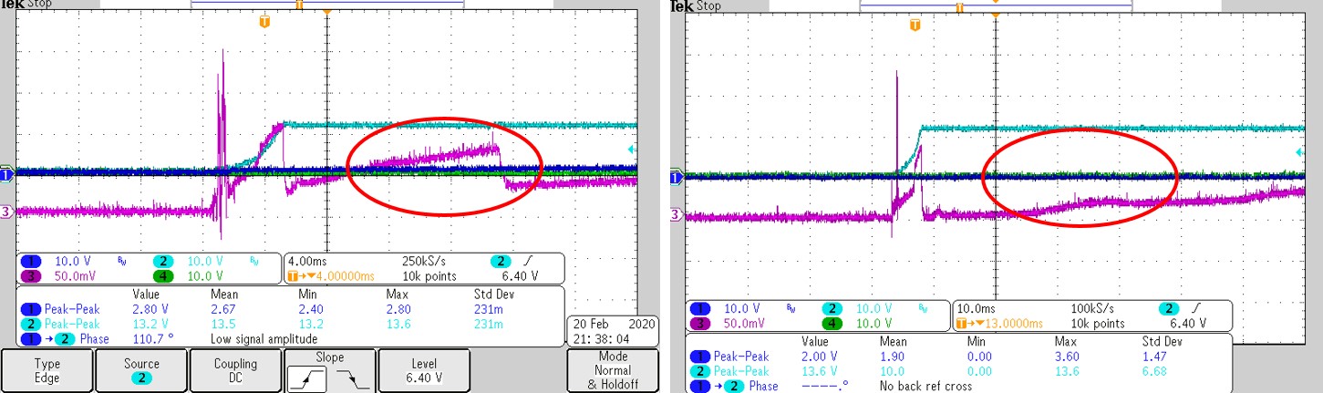
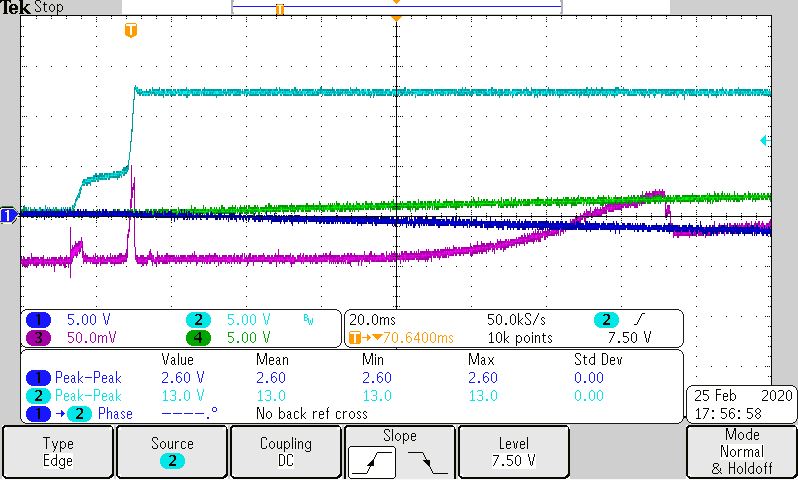
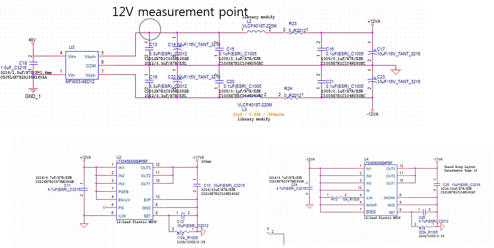
DC-DC (output specifications, ± 12V, 125mA) and LDO (output specifications, ± 11V) Inrush has occurred. 
(the figure on the Left , sky blue: DC-DC output + 12V purple :+ 12V current, blue :LDO + 11V) LDO is a soft-start(2.3sec) feature. circuit current ± 70mA
  If the OPA4192 is changed to the same model as the AD4084-4, no inrush current will occur as shown in the figure on the right.
  (If you quickly turn on / off the power, ± 11V will not turn on.)
  In my opinion, the operating voltage of the OPA4192 is from ± 2.25V, so when the power is turned off and turned on quickly,
 it is considered as the inrush current generated by the reverse of the remaining voltage.
Is my estimate correct?
Is it best not to use an op amp like wide supply op amp OPA4192?

Best regards,

Jimmy

  • Upload the photo again.

  • Hi Jimmy,

    Question:
     In my opinion, the operating voltage of the OPA4192 is from ± 2.25V, so when the power is turned off and turned on quickly,
     it is considered as the inrush current generated by the reverse of the remaining voltage.
    Is my estimate correct?
    Answer:
    OPA4192 IC design is based on CMOS, while AD4084-4 looks like BJT technology. So if you are talking about power on "inrush" current, it is NOT apple to apple comparisons. I suspected that this may be related to Shoot-Through Current at the Op Amp's AB output stage. if you send us the schematic, I can confirm the scenario. 
    Question:
    Is it best not to use an op amp like wide supply op amp OPA4192?
    Answer: 

    This is not a good assumption. Inrush current is present in any design circuit. The questions are " is the inrush significant". It is a typically measured  in percentage with respect to the nominal output current in a circuit.  What are your design requirements? In many application, inrush current has time duration and peak amplitude specification and requirements, especially in aerospace applications. Perhaps you can increase the Soft Start timing in LDO, and ramp up the output voltage and current slowly. Based on the your plot, I do not see that it is a concern. 
    BTW, in Power Input Test per DO-160 aerospace certification and requirements, the inrush current of a system can be as high as 9 times of the nominal output current for a duration of 100 usec or so, I recall. The inrush current limit requirements are used to prevent overheating of copper wires, and melting away the insulation material of wire harness. 
    If you have other questions, please let us know.
    Best,
    Raymond
  • Hi Raymond,

    Thank you very much for your response.


    One circuit diagram is power circuit and DC-DC is limited to small size.(3W)

    and To prevent in-circuit inrush current, LDO with built-in soft-start function is used.


     The other circuit is a filter and amplifier circuit where the op amp(OPA4192) is the cause of the problem.

    Because DC-DC thinks that there is no problem if the output capacitance capacity and load conditions are correct.

    Replacing the op amp only solves the problem.

    It is also because the DC-DC capacity is limited to small size.


    The first circuit diagram is the power circuit diagram.

    The second schematic is a filter and amplification circuit.

     
    Power boot problems occur 1 or 2 times during 50 power on / offs, and only 15 out of 100 circuits seem to happen frequently.


    the load current is ±75mA.

    Best regards,

    Jimmy

  • Hi Jimmy,

    I don't understand your scope plots. You say that the sky blue curve is the +12V output of DC-DC converter and that the blue curve is the +11V output of LDO. But when looking at the right scope plot I don't see +11V at the output of LDO. I only see a voltage which is zero plus a bit noise:

    Of course, in this case no inrush current can flow through the analog circuit, equally what OPAmp is mounted, because there's no supply voltage at all.

    In the left scope plot, on the other hand, the blue curve is slightly above zero, I guess 1.5V plus noise. In this case a current could flow, of course. But are you sure that this current is pulled from the OPAmp at all? Or maybe it's the inrush current of LDO itself?

    How and where do you measure the "inrush current"?

    Kai

  • Hi Jimmy,

    Kai has a very good point. Your +11V supply rail is not operating, if the attached schematic represents the actual circuit. In addition, 12V measurement point circled in the attached image above can not conclude the "inrush" behaviors of OPA4192, I assumed that OPA4192 is being powered by +/- 11Vdc rails. 

    The way that being measured, you can not claim anything about the OPA4192 power on/off behaviors. You have so many bypass capacitors on boards, the inrush current may be easily related to how these caps are charged or discharged during rapid power On/Off events. 

    The +11Vdc rail from LT3045 LDO, the input voltage is +12V, you will not get +11Vdc output as it is shown in the attached schematic. Your LT3045V's PGFB pin is connected at +12Vdc. The internal voltage comparator's reference is set at 0.3V, the output is not going to be +11Vdc. The PGFB pin's voltage needs to be ((Rpg1/(Rpga1+Rpg2))*11Vdc=0.3V, and your circuit does not have it. It is likely that you are getting 0V at the output of the LDO. Please check your -11Vdc LDO as well. 

    Best,

    Raymond

  • Hi, Kai

    Thank you very much for your response.


    The above two pictures show the 11V output normally. This is not because 11V does not come out, but because the soft start time is 2.3 seconds. Let's check again whether it is LDO inrush current.

    Please Undertand that for security reasons, you have cleared the circuit diagram.

    Best regards,

    Jimmy

  • Hi Raymond

    Is it a problem to disable PGF? 
    I know you can use soft star feature without using PGF.
    The output voltage was 11V with rset.

     Please Undertand that for security reasons, you have cleared the circuit diagram.

    and   I am going to try using the under voltage lock out function and reverse input protection function.

    Best regards,

    Jimmy

  • Hi Jimmy,

    The datasheet in  Note 10 in LT3045 did mention the pin state during a fault conditions. These pins must remain at the voltage > GND during normal operation according to the datasheet. 

    What is your current probe I to V scale factor? I recalled that the circuit has many capacitors from  the measured point to OPA4192 power rails, so it is hard to tell to tell where the issues are. 

    You may need to use high impedance DMM to probe the capacitors after the 12V measurement point, and see which circuits discharge the quickest after momentary power off/on. If you place a current probe at OPA4192 supply voltage rail, you may have better ideas what is OPA4192 is doing during the momentary Off/On conditions. The scope plot as shown is not conclusive at this point. 

    If you concern about the privacy, please send me an email through E2E, and I can support it via TI's internal email. 

    Best,

    Raymond

  • Hi Jimmy,

    I am going to close this inquiry for now. If you need further assistant, you may continue to post on the thread or open a new one. 

    Best,

    Raymond

  • Hi Raymond.


    I solved the problem by adding a UVLO circuit.

    The following picture is after applying UVLO.


    sky blue : DC-DC 12V output.

    green and blue : LDO ±11V output.

    purple : 12V current.

    UVLO threshold : 8V


    Best regards,

    Jimmy