This thread has been locked.

If you have a related question, please click the "Ask a related question" button in the top right corner. The newly created question will be automatically linked to this question.

OPA2205: Input bias current, input offset current and super-beta inputs

Part Number: OPA2205

Hello everyone,

I have some questions regarding the OP2205 op amp model to clarify my understanding of the op amp principle.

1. Does this model use Voltage FB or Current FB architecture? I'm having trouble understanding the input offset & bias current rating because a VFB amplifier would have a matched input bias current, hence Ios = Ib_plus - Ib_minus = 2*Ib. But the datasheet is showing the opposite with Ib=0.2nA & Ios=0.1nA so it is quite counter-intuitive for me.

2. I'm also learning more about the super beta inputs' advantages. As shown in the datasheet, is it because of this architecture that allows OPA2205 to have such low input bias current & input current noise compared to other op amp models? Is there any other advantages/disadvantages that this architecture brings?

Thank you very much. I am trying to learn so any suggestions, corrections would be very much appreciated.

Best regards,

Phong Phan

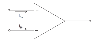
Edit: After looking more closely into the datasheet and other materials I figured out my understanding of the input bias & offset current are largely incorrect. I realize that input bias currents can be of the same or opposite direction depending on the op amp's input stages. So please ignore my #1 question.

  • Hello Phong,

    You ask a good question!

    Bipolar input operational amplifiers of conventional design will have a specific input current direction. Usually the current flow convention is such that the current is flowing into the input transistor bases of an NPN differential stage, and flowing out from the input transistor bases of PNP differential stage. The input bias current would have only one polarity for each case. That sign may be included in the Electrical Characteristics table input bias current specification and is often the case when the sign is negative such as -10 nA. The sign may not be included if the sign is positive.

    The OPA2205 input bias current (Ib) in the Electrical Characteristics table does lists the input bias current of ±0.2 nA typical and  ±0.75 nA maximum at TA = 25°C, and ±1 nA maximum for TA = 0°C to 85°C. Those limits indicate the input bias current polarity can be positive, or negative, and that is truly the case for the OPA2205.

    The OPA2205 input circuit on both the inverting and non-inverting inputs have additional circuitry referred to as bias current cancellation. As the name implies the circuitry is made to cancel the input bias currents and make them as small as possible. Bias current cancellation can be applied to conventional bipolar input transistors having typical betas (current gain) of ~ 100, or super beta transistors having betas in the thousands. The input current for a super beta transistor is already much less than that of a convention bipolar transistor because Ib = Ic / beta (for a equivalent Ic). However, adding the input bias current circuitry reduces the Ib even more. Since it is not possible to get exactly zero Ib, the cancellation can overshoot a bit and the input bias current can actually end up being the opposite sign of normal. See OPA2205 datasheet Figures 10 and 11 to see the typical Ib distribution.

    If you would like to learn more about input bias current cancellation see Section 2 of TI's Precision Labs - Op amps:

    https://training.ti.com/ti-precision-labs-op-amps-vos-and-ib-specifications?

    Another advantage of the super-beta transistor design is due to their very low input current, the input current noise can be much lower than what is achieved with conventional bipolar transistor input design. Certainly different bipolar transistor processes will have different current noise results so that needs to be taken into consideration. The OPA2205 input current noise is typically 200 fA/√Hz (f = 1 kHz ), which is very low for a bipolar input op amp.

    Regards, Thomas

    Precision Amplifiers Applications Engineering

  • Hello sir Thomas,

    Thank you so much for your reply. Your in-depth answer have definitely helped me to understand the topic and cleared all of my questions.

    Best regards,

    Phong Phan

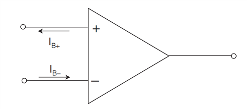
  • I have yet another question regarding the input bias current. Is there any case where at a same moment there exists two input bias current flowing in opposite direction?

    As illustrated in the picture below:

  • Hi Phong,

    Yes, that can be the case as I mentioned previously. The super beta op amp input transistors have the additional bias current cancellation circuits connected to each of the input transistor bases. Initially, when the super beta input op amp such as the OPA2205 is powered for the first time and the input bias current is measured the currents likely have the same polarity and flow in the same direction. Those Ib values are stored.

    Then when it comes time to minimize those individual Ib currents and adjust them as close to zero as possible the bias current cancellation circuits are called upon to add or subtract current from the measured Ib values. As the Ib currents are adjusted and brought close to 0 nA, it is possible over shoot 0 nA and end up with the Ib current having the opposite sign. That is because there is limited resolution and accuracy in the Ib measurement and adjustment system. When the Ib trimming is completed one input's Ib may be to one side of 0 nA, and the other may be to the other side of 0 nA having the opposite polarity. For example, one OPA2205 input may have an Ib of +0.2 nA, while the other input may be -0.2 nA. That case could be represented by your drawing. 

    Keep in mind because of the Ib cancellation and its limits the Ib could be positive for both inputs, negative for both inputs, or the opposite for the two inputs. In any case it is required to meet the Ib +/- limits published in the datasheet Electrical Characteristics table.

    Regards, Thomas

    Precision Amplifiers Applications Engineering