This thread has been locked.

If you have a related question, please click the "Ask a related question" button in the top right corner. The newly created question will be automatically linked to this question.

AFE032: Digital filter coefficients - custom filter

Part Number: AFE032


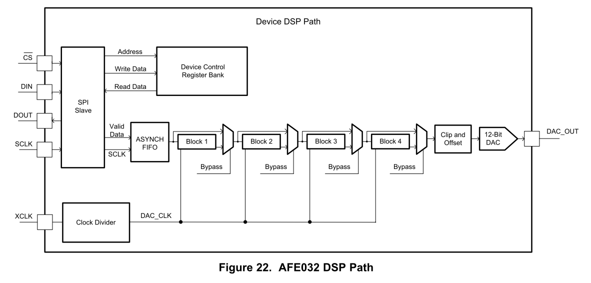
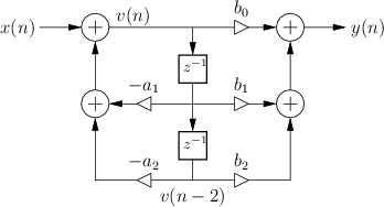
Hi, could you please describe the connection between the REG_COEFFx_BLOCK_x_xS registers and one of the two general digital filter canonical form coefficients:

canonical form I:  

canonical form II:

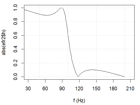
I found the filter coefficients for Figure 23 - Transfer Function of Block 2 - CENELEC A Band Coefficients According to Table 8 (SBOS669A, page 30) in R:

> e2 <- ellip(3, 1, 20, 95/200, "low", "z")
> e2
$b
[1] 0.2365224 0.3682327 0.3682327 0.2365224

$a
[1] 1.0000000 -0.3599084 0.7529883 -0.1835697

> plot(efr2$f, abs(efr2$h), type="l", xlim=c(30,210), ylim=c(0,1), xlab="f (Hz)", xaxp=c(30,210,6))

but cannot find the relationship between the filter e2$a and e2$b coefficients and register values

hex dec dec-sign norm
reg =HEX.DEC(A10)/16 =IF(B10>2048;B10-4096;B10) =C11/2048
1040 260 260 0,126953
0000 0 0 0
0CF0 207 207 0,101074
0000 0 0 0
06E0 110 110 0,053711
D180 3352 -744 -0,36328
0AC0 172 172 0,083984
0600 96 96 0,046875
0AC0 172 172 0,083984
2D20 722 722 0,352539
6960 1686 1686 0,823242

Thank you,

Attila

  • Hi Attila,

    I have to get back to you about the inquiry. Are you trying to verify the coefficient values in z domain through Matlab? If I provide you with the transfer functions in s domain, are you able to generate poles and zeros in Z domain. I do not work with digital filter settings in z-Transforms?

    Normally we are using passive 4-pole Bandpass filters for the incoming Receiving signals.  Although C2000 is capable to filter out the incoming signal through DSP path, I do not use DSP software feature, since we do the signal filtering and attenuation through hardware. 

    Best,

    Raymond

  • Hi Raymond,

    Thank you very much for your reply and care.

    In my first post I described that I found one of the realized digital filters in the TX path in Block 2 in Figure 22 (AFE032 datasheet page 27, SBOS669A):

    Actually earlier I found another realized digital filter in Block 1:

    # fig 24. block 1
    > e <- ellip(2, 1, 20, 400/600, "low", "z")
    > efr <- freqz(e, Fs=1200)
    plot(efr$f, abs(efr$h), type="l", xlim=c(100,600), ylim=c(0,1), xlab="f (Hz)", ylab="magnitude", xaxp=c(100,600,5),  mgp=c(1.8,0.6,0), xaxs="i", yaxs="i", col="red")
    > grid()
    > e
    $b
    [1] 0.5101542 0.9562067 0.5101542
    $a
    [1] 1.0000000 0.7890983 0.4285881
    attr(,"class")
    [1] "Arma"

    This graph is not copy-paste from the datasheet but was drawn by R independently with the given filter parameters: ellip(2, 1, 20, 400/600, "low", "z"):

    But again I cannot find the correspondence between these digital filter coefficients (what realizes the filter in DSP terms) and the recommended values in Table 7. Page 29 column ARIB.

    With these filters I just illustrated that the connection between the digital filter Canonical Form ai bi parameters (what the digital filter design algorithm spits out) and the AFE032 filter register values is not straightforward, actually not documented, what makes custom hardware filter realization in AFE Block 1 and Block 2 impossible.

    My goal is not to write a software DSP filter in the RX path that can be run on C2000 but to use the AFE032 hardware DSP filters in the TX path with other register values than Recommended Coefficient Values for Block 1 or Block 2 and other sampling freqencies than the Fs 400Hz and Fs 1200Hz belonging to Recommended Coefficient Values for Block 1 and Block2.

    So my question: if I design a digital filter and get the ai and bi Canonical Form coefficients, then how do I set REG_COEFFx_BLOCK_x_xS register values so as to realize this filter in the AFE032 Block1 or Block 2 hardware.

    Could you please help me with this problem?

    Thank you,

    Attila

  • Hi Attila,

    Question:

    My goal is not to write a software DSP filter in the RX path that can be run on C2000 but to use the AFE032 hardware DSP filters in the TX path with other register values than Recommended Coefficient Values for Block 1 or Block 2 and other sampling freqencies than the Fs 400Hz and Fs 1200Hz belonging to Recommended Coefficient Values for Block 1 and Block2.

    So my question: if I design a digital filter and get the ai and bi Canonical Form coefficients, then how do I set REG_COEFFx_BLOCK_x_xS register values so as to realize this filter in the AFE032 Block1 or Block 2 hardware.

    In Table 5 on p. 26 of AFE032 datasheet, there is R/W bit, which controls Read or Write in SPI mode. You need to follow the 16-bit command in SPI Mode to  Read/Write registers .  DATA0-DATA7, 8 bit of data is where SPI data is defined. If bit 15=1=read, then the returned DATA0-DATA7 is the content. If bit 15=0=write, then you place the data in DATA0-DATA7 in hex, which it will write to the defined register address ADDR0-ADDR6. There are approx. 75 registers (published) in AFE032. 

    The Data Resister Memory Map is shown in Table 13 of the datasheet. If the register is specified as R, it is read only register. If it is specified as R/W, it is designed to do both with the SPI command defined in Table 5. 

    From p.39 - p.60 define the register contents/definition, bit and structures. They are all 8 bit in length. These registers control the entire defined features in AFE032 IC. 

    From p.51 - p.60  defined how to Read or Write Reg_Coeff_Block Content (e.g. Table 39). You are able to read the content of entire registers. However, if part of  a register is defined as Read only, you are not able to Write it. Again, R/W means you can do both Read and Write per SPI command defined in Table 5. 

    If this is not clear, I can explain further. Please post the question and I will answer it. 

    I am still working on your previous inquiry, if you still interested to know. I have to find engineers who worked on the project, since many of them are not in the current team any longer. And your questions are very specific, and I know very little how z-transform works, but I do not know how to transform Laplace s-domain to z-domain or vice versa. Of course, Matlab is specialized in this area. 

    Best,

    Raymond 


  • Dear Raymond,

    Thank you very much for your reply.

    All you wrote is clear for me regarding SPI communication and how to write to REG_COEFFx_BLOCK_x_xS registers. My question is what to write to REG_COEFFx_BLOCK_x_xS registers when I have a custom designed DSP filter with ai and bi coefficients. That is, how to translate for example the filter 

    ellip(2, 1, 20, 400/600, "low", "z") 

    with coefficients

    $b
    [1] 0.5101542 0.9562067 0.5101542
    $a
    [1] 1.0000000 0.7890983 0.4285881

    to REG_COEFFx_BLOCK_x_xS values. In more detail: how will I get seven 4digit hexadecimal numbers to be written to REG_COEFFx_BLOCK_x_xS from these six real valued numbers listed above. What is the algorithm for that?

    Thank you for your efforts regarding Z and Laplace transform issues. I know these things, and I do not need help with the filter design. I need help only - as I mentioned above - how to translate the resulting digital filter to REG_COEFFx_BLOCK_x_xS values.

    Thank you for your efforts & best regards,

    Attila

  • Hi Attila,

    Yes, I am working on how the floating point is converted to hex numbers in the registers.  

    Could you send me a friend request via E2E so we can discuss the information in private email? Also, the information  you requested may take more than a few days. 

    Once we establish a connection via E2E private message, I am going to close this public inquiry, if it is ok with you. 

    Best,

    Raymond