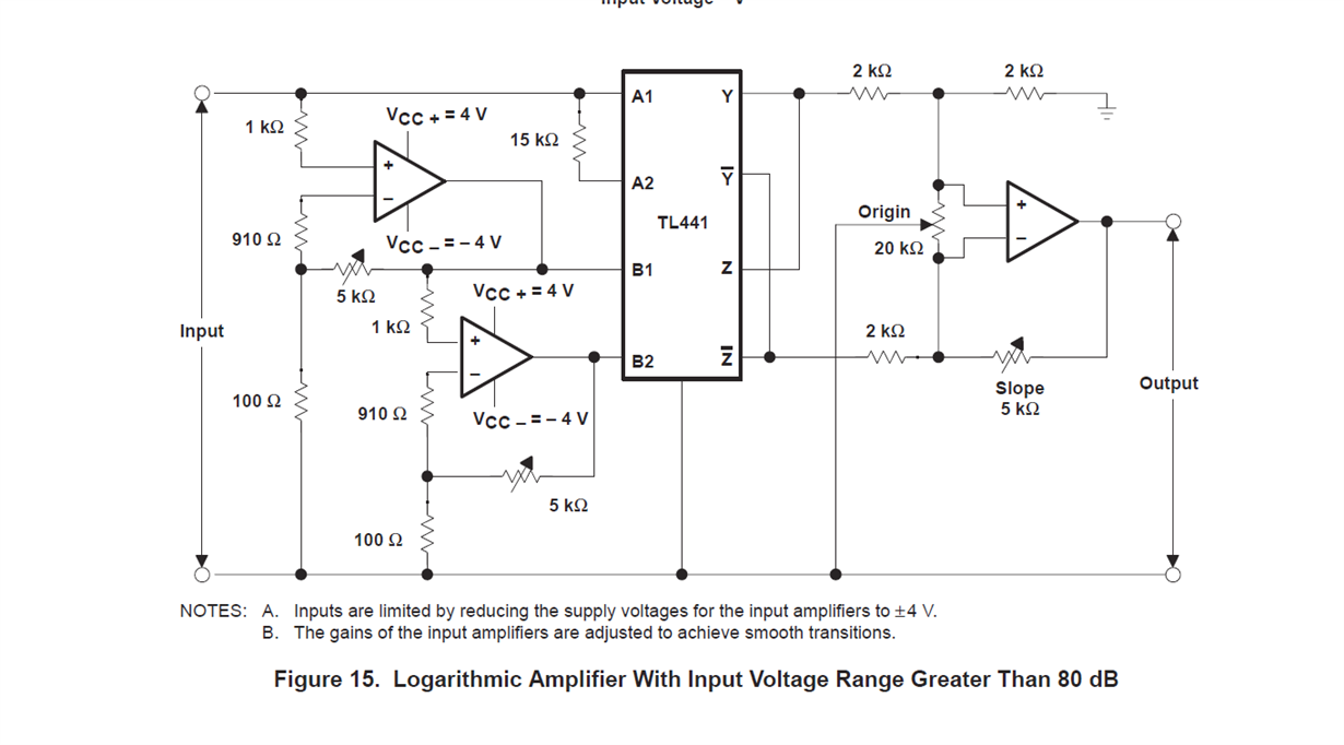
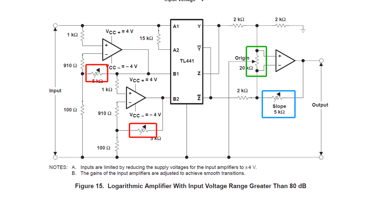
This figure is Figure 15 in the manual tl441,There are several adjustable resistors. I'd like to ask what determines the resistance value of these resistors? Are there any typical values recommended?
This thread has been locked.
If you have a related question, please click the "Ask a related question" button in the top right corner. The newly created question will be automatically linked to this question.
This figure is Figure 15 in the manual tl441,There are several adjustable resistors. I'd like to ask what determines the resistance value of these resistors? Are there any typical values recommended?
Hi Zhang,
The TL441 is a legacy multiplier and we have no information beyond the datasheet. The datasheet provides a general explanation of the adjustments "Four compensation points are available to allow slight variations in the gain (slope) of the two individual 15-dB stages of input A2 and B2. By slightly changing the voltage on any of the compensation pins from their quiescent values, the gain of that particular 15-dB stage can be adjusted to match the other 15-dB stage in the pair. The compensation pins also can be used to match the transfer characteristics of input A2 to A1 or B2 to B1."
We can see that the two 5 kilohm potentiometers on the left side of Figure 15 are in the feedback loop of the two op amps. They provide the gain (slope) adjustment on the input side. The potentiometer across the output op amp provides the origin which appears to be a simple way to adjust the output offset. The datasheet states "Differential-output-voltage levels are low, generally less than 0.6 V. As demonstrated in Figure 12, the output swing and the slope of the output response can be adjusted by varying the gain by means of the slope control. The coordinate origin also can be adjusted by positioning the offset of the output buffer." The potentiometer in the feedback loop sets the gain of the output stage in conjunction with the 2 kilohm input resistor.
Regards, Thomas
Precision Amplifiers Applications Engineering
Hi Zhang,
the nominal value of the two red resistors would be 3.062k to provide a gain of 30dB. For the blue and green resistors nominal values do not exist because these two resistors are used for output scaling. See figures 12, 13 and 14 of datasheet.
With the todays ultra-low-input-current precision FET- and CMOS-OPAmps the two 910R resistors would no longer be needed.
Kai