This thread has been locked.

If you have a related question, please click the "Ask a related question" button in the top right corner. The newly created question will be automatically linked to this question.

TCAN4550-Q1:Current in CAN line

Part Number: TCAN4550-Q1
Other Parts Discussed in Thread: TCAN4550, TCAN4550EVM

Hi Team,

My customer is going to artwork the CAN bus line on the PCB with a differential impedance 120 ohm line.

Since it is a 120 ohm line, it will be quite thin, but what is the current flowing through the CAN line?

I think it is the following calculation when DOMINANT. 

 (CANH - CANL)/R = (3.5 - 1.5)/120 = 16.7mA

Is it correct?

Best Regards,

Kenji

  • Hi Kenji,

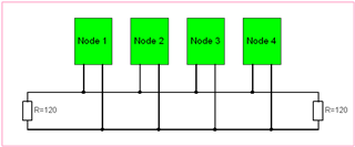
    there are two 120R resistors Relaxed

    So it will be twice your calculated current.

    Kai

  • Hi Kenji,

    These are both correct for certain conditions, but let's consider the some worst-cases to ensure that the traces can handle all possible conditions. 

    In the worst-case non-fault condition, the transceiver will be driving a voltage close to 5V over a maximum load of 52-ohms (two 120-ohm resistors like Kai pointed out, plus the load of the maximum number of transceivers on the bus). This would result in a current of 96mA between CANH and CANL. Note that about half of this current would only travel to the closes 120-ohm resistor. 

    In certain fault cases, the current from the driver can be even higher. If for instance the CANH line was shorted to ground (low impedance path, Rload ~= 0-ohm), then the transceiver would need to limit the output current to avoid damage. TCAN4550 specifies a maximum bus fault current of 100mA for this purpose. I would recommend using traces that can support this maximum current without damage to account for such fault cases. 

    Let me know if you have any more questions.

    Regards,
    Eric Schott

  • Hi Eric-san,

    Thank you for your great support.

    My customer is trying to design a differential 120Ω pattern.

    The pattern width of 0.1mm is 100mA current.

    There seems to be no margin for the current, but is this design correct?

    TCAN4550EVM does not seem to care about the pattern width that much.

    Should the customer lower the impedance a little more and design it so that the current can flow?

    I would like to know the best wiring layout for my design.

    Best Regards,

    Kenji

  • Hi Kenji,

    As the 96mA is using all of the worst-case specifications, I don't expect any real system would see this amount of current during normal operation. For pattern designs meant to service typical systems, 100mA capability will suffice. Some fault conditions could create currents larger than this, but these states should not persist for sustained amounts of time. 

    I'm not sure how the bus traces were designed on the EVM, but since this board is mainly used for functionality evaluation, there are many sub-optimal characteristics that should be avoided in a real system. For instance, the header pins make for easy connections for probing, injection, and termination selection, but also introduce stubs and inductance to the traces that negatively impact signal integrity. While some aspect of this design are meant to be emulated in practice (such as schematic circuitry and components), some aspects of the layout are made with ease-of-use prioritized over being functionally optimal.

    In a multi-point cable harness, stub nodes are kept to a minimum with short lengths from the main signal path. It's common to daisy-chain nodes to ensure these stubs are as short as possible. Termination should be placed at the end-nodes or end of the cable at the two furthest points to most effectively dampen signal reflections. 

    Feel free to submit any layout diagrams for review. 

    Regards,
    Eric Schott

  • Hi Kenji,

    I don't see issues with 0.1mm width:

    https://www.7pcb.com/trace-width-calculator.php

    Having said this, increasing the copper traces' width to 0.15mm should also work:

    https://www.eeweb.com/tools/edge-coupled-microstrip-impedance/

    Kai