This thread has been locked.

If you have a related question, please click the "Ask a related question" button in the top right corner. The newly created question will be automatically linked to this question.

INA3221 to Read three 4-20mA sensors

Other Parts Discussed in Thread: INA3221

I would like to hear opinion about using Current Shunt Monitors like INA3221 (triple channel I2C CSM) to read three 4-20mA sensors. Especially in regard to the filtering of the digital HART signal that is modulated on the same loop. Could that be done using the averaging function?

In the IC page it is stated that this IC is "Low-side Capable" while in the datasheet this hasn't been mentioned. Will this be a factor in the design? 

  • Edd,

    To understand if this device will work in your circuit, it comes down to how much error you are willing to accept.  Let me explain a little bit.

    Current shunt monitors like the INA3221 have front end circuitry that is not like a traditional instrumentation amplifier or op-amp.  Because the current shunt monitors like this one need to accommodate common mode voltages above supply, the front end will actually take a little current from the inputs to power the front end and provide the headroom for the internal circuitry to work.  When the supply is putting out AMPs of current, a little siphoned off to make the chip work is not very noticeable.  When it's mAMPs, it can be moreso, usually showing up as an offset error.

    This, coupled with other architectural differences lead to high input bias currents and often unmatched input bias currents.  For example, the INA3221 has 10uA on the IN+ pin and 10uA || 670kOhms for the IN- pin.  The 10uA on each pin is relatively well matched, but any mismatch through the sense resistor will add error; either offset, gain, or both depending on the Ib stability.  The 670kOhms is basically tied to ground, so there will be a little current into the IN- pin generated by the voltage at IN- to ground.

    Low currents also mean larger sense resistors to get an adequate LSB step and full scale range.  Ideally, these resistors are in the mOhm range.  1A at 10mOhm is 10mV, which is easy to measure and doesn't get as affected by uA bias currents and such.  10mA at 1Ohm is also 10mV, but 1Ohm can create more sense voltage errors from small currents.  It's not terrible, but it's not ideal.  You can calculate a general idea of the errors expected from the specifications, checking the CMR, PSR, temperature, bias currents, offset, and gain error for your range of operation and setup.

    I've not worked with HART based technologies before, but it appears to use modulated signals of 1.2kHz and 2.2kHz to indicate 1s and 0s.  The INA3221 has a fastest sampling rate of 140uS typical for one channel, so that would be 420uS for all three, assuming no padding is needed between the samples and data output.  Assuming 420uS, that would be 2.38kHz, which is barely able to get one sample per 2.2kHz cycle and only 2 per 1.2kHz cycle.  The internal clock of the INA3221 is trimmed but not 100% accurate, and this will make synchoronozation difficult if you are trying to read each bit specifically.

    That is just if you measure the sense voltage.  If you also need to measure the bus voltage, you can double that sample time.

    What kind of master I2C device do you have?  It will need to keep up with the data flow coming out of the INA3221, and I am not sure what kind of speed with which you want to sample, but that should be a factor in your design as well.  The INA3221 can sample for long periods of time with lots of averages

    If you are just trying to get an average current reading while the line oscillates at AC, you can certainly use the averaging and just understand that there may be a slight error between readings depending on the number of full and partial cycles are captured.  As for filtering, I'm not sure I understand--could you elaborate?

    Finally, low-side capable is certainly available.  Generally people are more concerned with high-side sensing to avoid putting a sense resistor in the current path to ground from whatever load they are trying to measure, and are therefore interested in how high a source voltage can be accepted.  With such low currents, I'm not sure how this will affect the measurements--I suppose it would show up as an error or possibly noise, depending on the load and the bounciness of the ground.

    If you would like to fill me in on some more of the details of your design, I can certainly try to better assess your application requirements and try to make the best recommendation possible or find someone else here who can support you too.

    I hope this helps, I look forward to your response.

    Best regards,

    Jason Bridgmon

  • Hi Jason,


    Thanks for the reply, it was very helpful.

    I want to filter out the HART signal, not to read them. I want to use the averaging to keep the readings stable.

    I don't have to get a high rate of readings, my uController is atmega2560 at 16MHz.


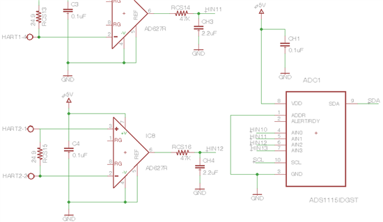
    The application doesn't requires a resolution or precision more than 1%. Do you think this IC is the way to go? My current design utilize Instrumentation Amplifier AD627 InAmp from Analog Devices and RC filter to eliminate the digital HART signal that is coming from the sensors and TI ADS1115IDGST 16 bit delta-sigma ADC with I2C interface to uController. As shown in the following diagram. But I'm looking for something with lower cost, to read 6 sensors. Do you think there is a better approach ?


  • Hi Edd,

    The requirement and need to remove the digital overriding HART content on the 4-20mA changes the discussion a bit here.  Jason’s previous comments on conversion timing were directed more in an effort to be able to discern the digital content so I will add on here based on this update. 

    The INA3221 features a delta-sigma front-end so this will actually help here as the ADC will effectively aide in averaging the input signal during the conversion period.  To reduce the AC component in the measurement the conversion time should be set to the longest conversion setting (8.244ms). 

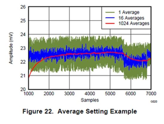
    The additional Averaging Function can also be helpful in further reducing the HART signal’s impact in the averaged measurement but there is a point to be aware of.  The averaging function for this device is designed to limit the effect noise and unwanted transient signals have on any single signal measurement.  This function results in a sort of a building up of the averaged value.  The algorithm used in the INA3221 involves bringing in the previous data output register value (this is zero for the first sample) and adding it to a divided down new sample (divider based on the average #).  This new appended average is then pushed back to the output data register so it can be read.  From this sequence where the output register’s POR value is zero and the averaging number is set to 1024 it will take the number of sample conversions equal to the average # setting to reach the full nominal signal level.  This is shown in the graph here taken from the INA3221 datasheet.

    One last point to clarify is the effect the INA3221’s input bias current will have on the 4 to 20mA signal.  The input bias current for each of the input pins on the INA3221 is nominally 10uA with a resistor divider on the IN- pin that will add some extra current on top of the 10uA based on the common-mode voltage (I = VCM / 670kohm).  The bias current will subtract from the signal current so this can be seen as a leakage or load on the 4-20mA signal.  A 4mA current signal would be reduced by 20uA to 3.98mA (assuming a low-side configuration) following the INA3221. 

    In all, the INA3221 can be configured to account for the HART signal and should help in reducing the component count as well.

  • Thanks so much Scott, that was really helpful. I will order the evaluation board, and try it with the sensors.