This thread has been locked.

If you have a related question, please click the "Ask a related question" button in the top right corner. The newly created question will be automatically linked to this question.

INA282 shunt or ground noise might randomly trip MCU current faults comparator from very fast output spike.

Guru 54778 points
Other Parts Discussed in Thread: INA282, INA240, DRV8305, INA301, TM4C1294NCPDT

Have issue 12.5Khz PWM ground noise at 25mv 45amp full scale shunt (low side monitor) may be amplified by INA282.  A much higher pulse is used to trip analog comparator when current rises above preset fault trip threshold. 

Will adding a 1nf capacitor to ground load side INA inverting input cause the precision to change or any other internal problem with shunt measures?

Scope capture of INA output signal taken at output resistor divider: Notice single very fast 30-40us FET on pulses rise above the average 1.04ms PWM cycle current period. Scope can only trigger on one pulse at a time even at 10k samples depth but notice these pulses originate all along the average current slope near 200mv. 

  • BP101,

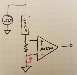
    I just want to confirm your schematic (drawn in black) and your capacitor proposal (drawn in red).  Can you please let me know if I got them correct?

    I'm a little confused I think since you're in low side configuration but want to put the capacitor on the negative input terminal, which is just ground to ground and probably ineffective, so I'd appreciate the clarification.

    Filtering out the PWM noise with a capacitor on the positive input to ground would just look like a differential cap across the inputs, so that should be ok.  We typically spec cap load on our output drivers but the inputs are fairly high impedance so direct filtering is allowable.  I'm confirming with design that 1nF will be acceptable, please bear with me while I get that answer.

    I want to plug another part of ours that just came out this month, the INA240.  It's got enhanced PWM rejection circuitry and really great CMRR specs; for your PWM applications (if I remember them correctly) it might be a really good fit.

    Let me know about that circuit diagram, and as always, we're happy to help.

  • Hi Jason,

    Meant to infer a 1nf capacitor on and directly across (+/-) INA inputs, (+) input near ground. Also the PWM transient response pulses above 159mv are the actual measured peak FET avalanche current, not the average lower current of 1.04ms cycle.

  • Hi Jason,

    Reviewed INA240 datasheet and our motor phase is above +80v, wouldn't the shunt amplifier blow up inline phase mode? If so might be nice to put a warning in figure 33 not to exceed +70v to maintain a +10v safety margin.

    BTW: Figure 33 shows a 100m shunt then states below 10m ohm was selected, why not show what was selected?
  • Hello BP101,

    I confirmed that adding a 1nF cap across the inputs shouldn't affect the measurement too adversely. Are you planning to make a filter with it by adding some series resistance? If so, that can add some gain and offset error to the measurement, but it might also clean up the signal more as well.

    Regarding the INA240--if your application goes above 80V, then yes, inline placement would not work. However, the common mode input is survivable up to 90V so it is ok to go to 80V with a 10V safety margain.

    You are correct that figure 33 and the text are not aligned. Both should read 100mOhms. Thanks for catching that!
  • Hi Jason,

    The false trips were being caused by PWM clock sync related issue. Was not planning to add any more series R being 6k already internal INA282. Have noticed 1nf being placed across inputs of the DRV8305 current monitors at the die and other Opamp current monitors tied direct to ground in the latter.

    Please explain what a filter might help as video seminars state no purpose for them. My guess is a ceramic filter might ward off undesired AC noise from entering differential amplifier inputs, in the frequency range of filter capacitor?

    BTW: Assume all test graphs CMM voltages are in millivolts? Had to think about that drop could go into volts with higher resistance shunts but then again I would be assuming.

  • BP101,

    Adding a capacitor across the inputs (or a pair of resistors and a capacitor to adjust the time constant) will filter out undesired AC noise at the inputs, as you say. I suspect it would smooth out those large spikes you see somewhat as well. Some people prefer to filter on the output of the CSM, having gained up the noise in the signal but sometimes it's needed for driving ADCs directly without buffering; it's all application dependent really how you configure your filters.

    I believe that most graphs involving the inputs of our current shunt monitors are in mV since generally we have fixed gains of 20 to 1000, so multiplying volts on the input just rails out the device prematurely.

    I was speaking to some colleagues of mine and we agreed that for low side motor control (instead of inline with the INA240 which didn't reach your full common mode range), you might look into the INA301 as well, assuming you haven't already.

    Hope that helps, let me know what else I can assist with!
  • Hi Jason,

    The INA301 can not be summed such as the old XMAS lights many had enjoyed years past. lol
    That option INA282 makes MOSFET inverter power blocks KW range reality, distributing current load across several chained inverters. That was our goal since MOSFET technology hundreds volt range still remains with fairly high RDS and mostly GTO's and AC induction motors are the rule.

    Mobile technology today simply leave an all electric vehicle stranded if the inverter crashes beyond recovery. That aspect seems risky to me and someone could make some aspect of transport possible even at reduced speeds. Not impressed with the one inverter mentality many have taken in the rush of product to market. So if a power block fails along the way simply plug in a spare or make it hot pluggable or even automated.
  • Ah, I see. Thank you for the clarification and insight into your application! I do appreciate it.
  • Hi Jason,

    Have added 1nf capacitor across the shunt which seemed to arrest some of the worst faulting aspect. Perhaps random faulting might relate to the INA282 output signal traversing  200mv below ground into SAR single ended analog channel mux TM4C1294NCPDT.

    Have purchased a few 3v3 TVS but have not installed them on the ADC inputs after seeing the INA signal at times traverses below ground.