This thread has been locked.

If you have a related question, please click the "Ask a related question" button in the top right corner. The newly created question will be automatically linked to this question.

INA250: What is the problem in my design that has burn many INA250A4 chips?

Part Number: INA250


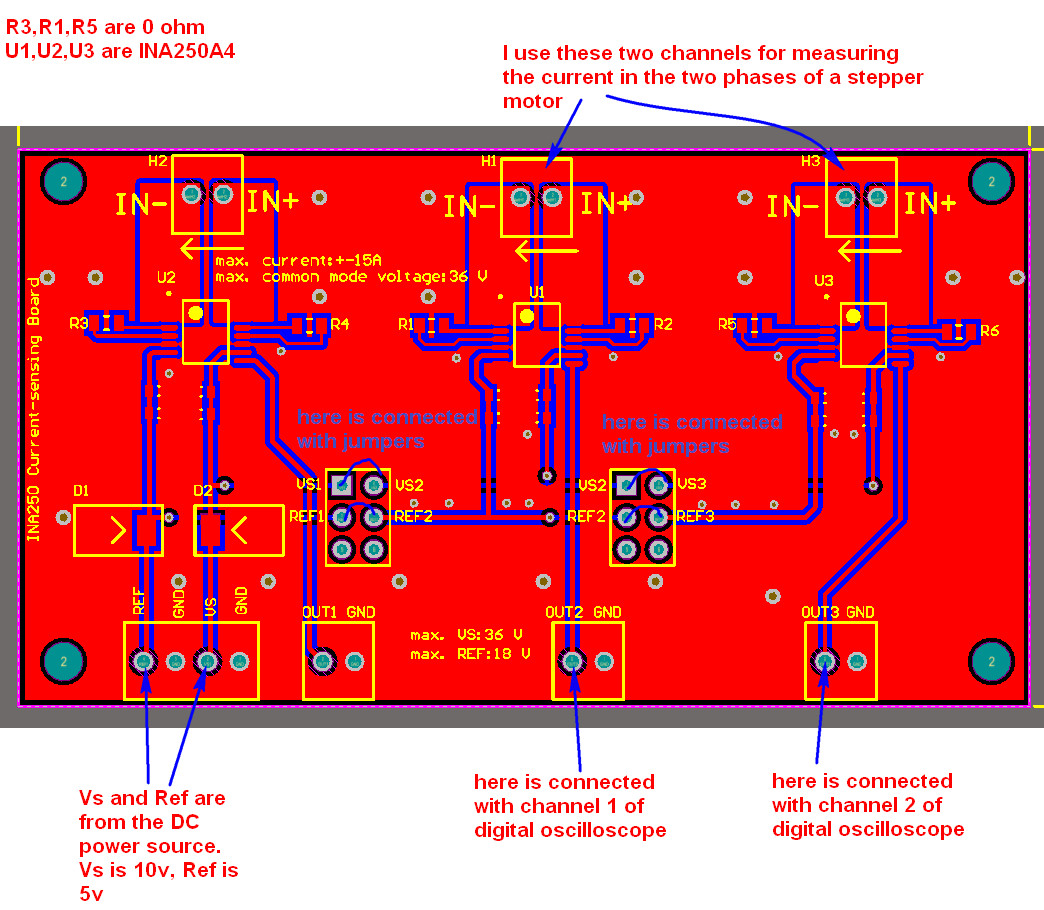
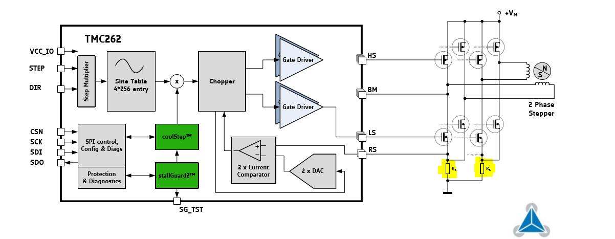
I use this board to measure the current in the two phases of stepper motor, using the right two channels. I call these two channels, H1, H3, respectively.

If I only use H1 channel, the measurement is ok. If I only use H3 channel, the measurement is also ok. When I use these two channels simultaneously, the INA250A4 chips in H1 and H3 channels will be damaged.

Please help me find where the problem is in my design. And the schematic file and Altium Designer PCB project can downloaded from .

Thank you. 

  • Yunlong,

    Two questions to start: 1. Is this a fast ramping pwm signal to the stepper motor? 2. When you say damaged and burned, do you mean the parts are physically hot, or that they have stopped working and need to be replaced?
  • Hi Jason,

    Thanks for your reply.

    For question 1,

    The stepper motor driver chip I use is,

    For question 2,

    I did the test again, and I found that the chips are not damaged. They are still in good condition.

    After doing many tries, I found that the problem is I can only use INA250 to measure only one phase current of the stepper motor. If I measure the two phases currents of the stepper motor, the stepper motor will not rotate. After trying many times, I found that the circuit of INA250 for measuring phase A of stepper motor cannot have the Ground with the circuit of INA250 for measuring phase B of stepper motor. I don't know why they cannot share the same ground. Please help me.

    Thank you.

  • Hi Yunlong,

    As per the datasheet you linked RS should be measured at the output of the Pins SRA and SRB. I suspect you are trying to break the wiring going to the motor coils and perform the measurement there. This wont work as each phase is fed an alternating current with the same amplitude as your DC-LINK bus (supply voltage) and the phases are offset. If you try to share a common ground you are short circuiting one of the phases.

    This is different from the configuration typically employed in brushless DC motors, where a PWM with a duty cycle of 50% on all phases is employed when no output is required. Each phase then sits at 1/2 of the supply voltage and hence no current flow occurs. By increasing or decreasing the duty cycle a voltage difference and hence a current sink or source between phases occurs, but the overall output is always within GND and the supply voltage.

  • Hi Carlos,

    Thanks for your help. I know that you are right, but after careful thinking, I still don't understand the meaning of this sentence "If you try to share a common ground you are short circuiting one of the phases."  Why? Could you explain that in detail?

    Thank you.

  • Hi Carlos,

    Could you explain the reason of the short circuit with details?

    Thank you.

  • The H bridge turns the phases for the stepper motor 180degree out of phase, therefore it creates an alternating signal at the output of the motor driver.

    Looking at the figure below, for your chosen controller, you see that each 'of the 4 outputs that lead to the stepper' is connected to two mosfets in a half bridge configuration. One leading to GND and one to VCC. By arranging these switches either of the outputs might connect to VCC or GND, so that an alternating output waveform is generated

    If your measurement board, the oscilloscope, or any similar device measuring currents has a common path to GND then when the top mosfet connects that output to VCC a short circuit will occur. The only way to measure this is by performing a differential measurement.

    You will need to redesign your circuit, so that it measures the current on the mosfet return path to GND, as indicated by the highlighted sense resistors below.

    Alternatively, if you still wish to proceed with the measurement on the motor phases the circuit needs to be re-arranged as to perform a differential measurement. Do be aware this method will also monitor the freewheeling currents and will result in the measurements being both positive and negative, given the nature of the alternating output. This in turn will add to the complexity, as the original currents will have to be reconstructed by syncing the mosfet on/off time with the respective readings.